
Method of triggering functions in a computer application using a digitizer having a stylus and a digitizer system

a technology of a computer application and a stylus, applied in the direction of user-computer interaction, input/output, instruments, etc., can solve the problems of not being able to adequately control the activation of the desired function with such a method, and not being able to provide adequate control of triggering a function,

Active Publication Date: 2010-03-23
WACOM CO LTD
View PDF34 Cites 67 Cited by
  • Summary
  • Abstract
  • Description
  • Claims
  • Application Information

AI Technical Summary

Benefits of technology

The present invention is about a way to trigger functions in a computer application using a digitizer and a pointing device. By applying pressure to the digitizer and sensing the pressure, the method can trigger different functions based on the pressure threshold. This allows for more complex and precise triggering of functions in the application. The invention also includes a digitizer system with a digitizer and a pointing device for applying pressure, and a sensor to sense the pressure. This system can also trigger different functions based on the pressure threshold.

Problems solved by technology

However, this results in a relatively small amount of friction to hold the tip 22 in place at a particular point on the digitizer surface 18 during the double click action.
The prior art fails to disclose a method for triggering a function, such as a double click action, using a digitizer and a pointing device, such as a stylus, which avoids the above noted problems.
However, the user is not able to adequately control activation of the desired function with such a method, given the user may inadvertently maintain contact between the pointing device and the digitizer.
However, such designs do not provide adequate control for triggering a function, such as a double click, given the user must manipulate the button, which affects user control of the stylus, or causes a release in force between the stylus and digitizer.

Method used


Image

  • Method of triggering functions in a computer application using a digitizer having a stylus and a digitizer system
  • Method of triggering functions in a computer application using a digitizer having a stylus and a digitizer system
  • Method of triggering functions in a computer application using a digitizer having a stylus and a digitizer system

Examples


first embodiment

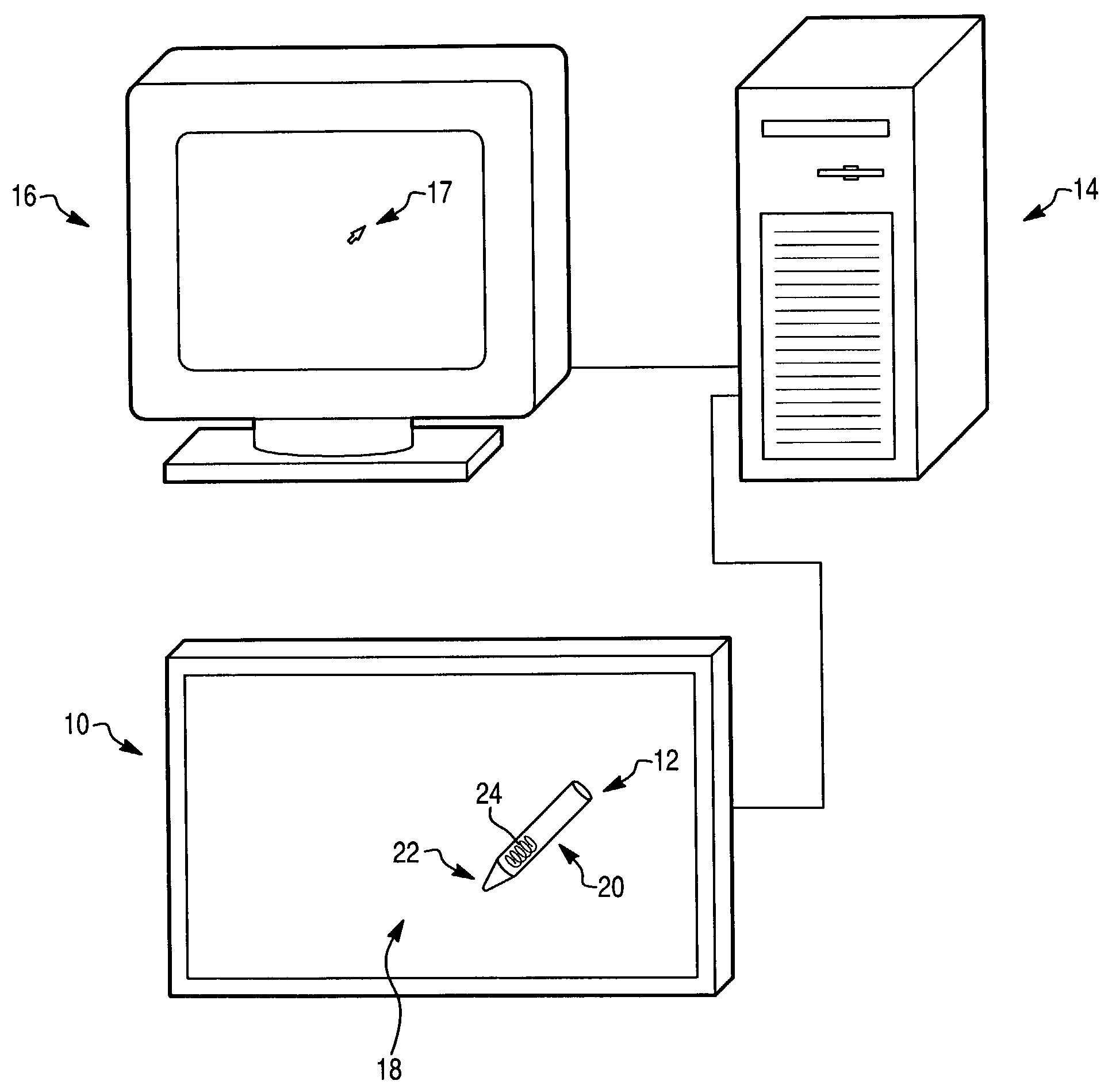
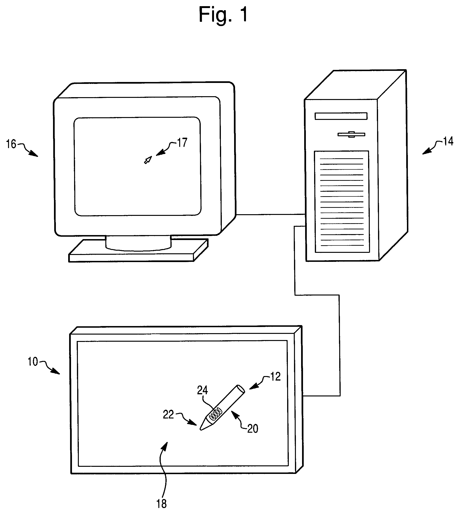
[0030]In the disclosed invention, sensor 24 operates like a switch having an open position and a closed position, similar to a button on a mouse. Sensor 24 is operably associated with tip 22 of stylus 12, as best shown in FIG. 1. Sensor 24 senses applied pressure P when tip 22 is depressed onto surface 18 of digitizer 10. Tip 22 is thereby depressed into body 20 of stylus 12. Sensor 24 then communicates the sensed applied pressure P to computer 14, which corresponds to a switch in a closed position. A closed switch is equivalent to a “press” action, as defined above. An open switch is equivalent to a “release” action, just as a mouse button may be pressed and released. Computer 14 has an operating system, preferably the Windows™ Operating System, or the MacIntosh™ Operating System, having an application including the double click function.

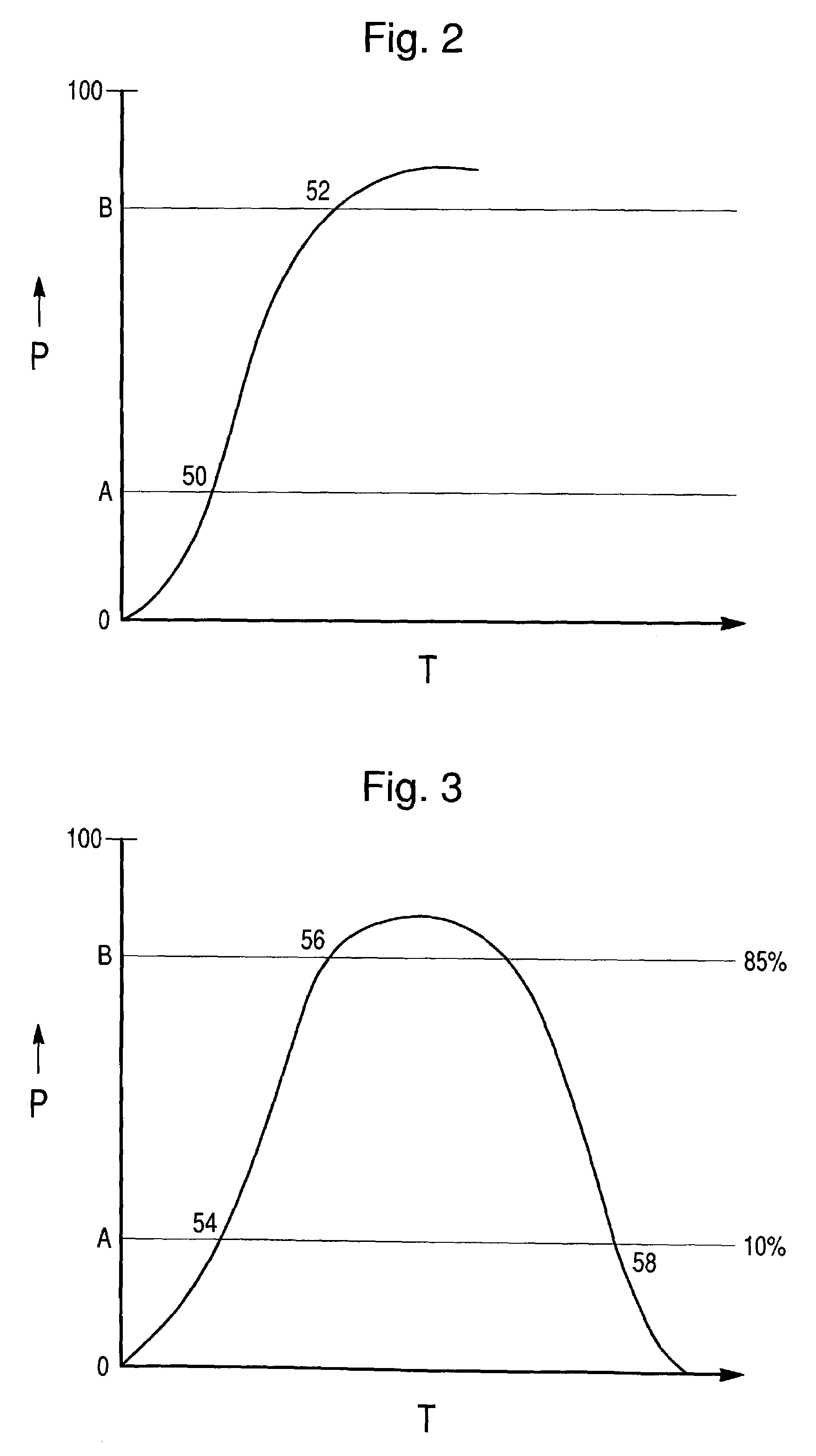
[0031]As best shown in FIG. 3, a first function is triggered if sensor 24 senses applied pressure P that exceeds a first pressure threshold A, whi...

second embodiment

[0036]The second embodiment may be beneficial for certain applications wherein a constant pressure is applied on surface 18 with stylus 12, such as for drawing. The application may also require that the user apply variable pressure. First pressure threshold A may be set very low, for example less than 5% of the total force range, while second pressure threshold B may be set very high, for example at least 95% of the total force range. With the preferred settings, the user may then maintain continuous contact with stylus 12 on surface 18, and apply variable amounts of force to surface 18, without unintentionally triggering a second function such as a double click.

third embodiment

[0037]In a third embodiment, a second function is only triggered if the sensed applied pressure P exceeds the second pressure threshold B at a particular point at which the first pressure threshold A was exceeded. Therefore, the second function will not be triggered if the sensed applied pressure P exceeds first pressure threshold A at a first point, and thereafter the sensed applied pressure P exceeds second pressure threshold at a second point.

[0038]Depending on user preference, as well as application specifications, the particular point at which the second function may be triggered may be a particular location on display 16 where pointer 17 is displayed when first pressure threshold A is exceeded, as best shown on FIG. 1. This particular point may be defined by a certain area of pixels, or preferably by a particular area such as an icon or menu area displayed on display 16, as used in Windows™ operating systems. Therefore, an area proximate to the particular point indicated by po...


PUM


Abstract

A method of triggering functions in a computer application comprises the steps of: providing a digitizer having a pointing device, wherein the digitizer and pointing device are operably associated with a computer having an operating system and an application; applying pressure to the digitizer with the pointing device; sensing the applied pressure; triggering in the application a first function if the sensed applied pressure exceeds a first pressure threshold; and triggering in the application a second function if the sensed applied pressure exceeds a second pressure threshold. The second pressure threshold is greater than the first pressure threshold.

Description

FIELD OF THE INVENTION[0001]The present invention relates to a method of triggering functions in a computer application by applying pressure to a digitizer using a pointing device, such as a stylus or an airbrush. The applied pressure is sensed, and a first function is triggered if the sensed applied pressure exceeds a first pressure threshold. A second function is triggered if the sensed applied pressure exceeds a second pressure threshold.DESCRIPTION OF THE PRIOR ART[0002]User interface applications for computer systems can receive input from both pointing devices and keyboards. A user may prefer to interact with an application by using a pointing device. As commonly known in the art, a pointing device is a tool that lets the user move a pointer around on a display. The pointing device also has some means of activating a displayed object under the pointer. The pointing device allows the user to directly manipulate the displayed objects. Rather than entering a keyboard command for ...

Claims


Application Information

Patent Timeline
Patent Type & Authority Patents(United States)
IPC IPC(8): G06F3/00G09G5/00G09G5/08G06F3/03G06F3/041G06F3/038
CPCG06F3/03545G06F3/038
Inventor FLECK, DAVIDYAMAMOTO, SADAO
Owner WACOM CO LTD
Learn More