Cantilevered motorcycle frame

a frame and motorcycle technology, applied in the field of cantilevered open loop motorcycle frame assemblies, can solve the problems of frame elastic deformation or breakage, and achieve the effect of high rigidity

Inactive Publication Date: 2010-03-23
PLOURDE SCOTT
View PDF10 Cites 1 Cited by
  • Summary
  • Abstract
  • Description
  • Claims
  • Application Information

AI Technical Summary

Benefits of technology

[0006]It is an object of the present invention to provide a construction of a motorcycle frame having a high rigidity capable of withstanding transverse bending and torsional forces as well as vertical forces applied to the frame during on and off-road riding.
[0009]Even another object of the present invention is to apply an air damped rear suspension which provides the classic appearance of a rigid, hard-tail motorcycle frame while still permitting substantial flexing between the top tube and rear swing arm assembly of the motorcycle.
[0012]The motorcycle frame includes the top tube supported by at least another support tube having a smaller radius than that of the top tube and welded to a lower portion of the top tube in a substantially parallel and concentric arrangement from the head tube to a point where the top tube diverges from the support tube to respectively form a drop seat and an engine support of the motorcycle. Therefore, the motorcycle frame has a generally planar construction that can be easily worked and a provide the necessary rigidity capable of withstanding transverse bending as well as torsional and vertical forces.
[0013]Secondly, the top tube defines a drop seat rail for supporting a seat, connected to the rear portion of the top tube at point vertically closer to the bottom frame rails than the upper most, or crown portion of the top tube. One end of the top tube connects to the rear swing arm support to define the cantilevered top tube extending in a vertical plane along the longitudinal axis of the motorcycle, the frame including the seat rail has a simple planar framing and has a high rigidity capable of withstanding transverse bending, vertical and torsional forces.

Problems solved by technology

If the frame is not rigid enough, the frame may elastically deform or break.

Method used


Image

  • Cantilevered motorcycle frame
  • Cantilevered motorcycle frame
  • Cantilevered motorcycle frame

Examples


Embodiment Construction

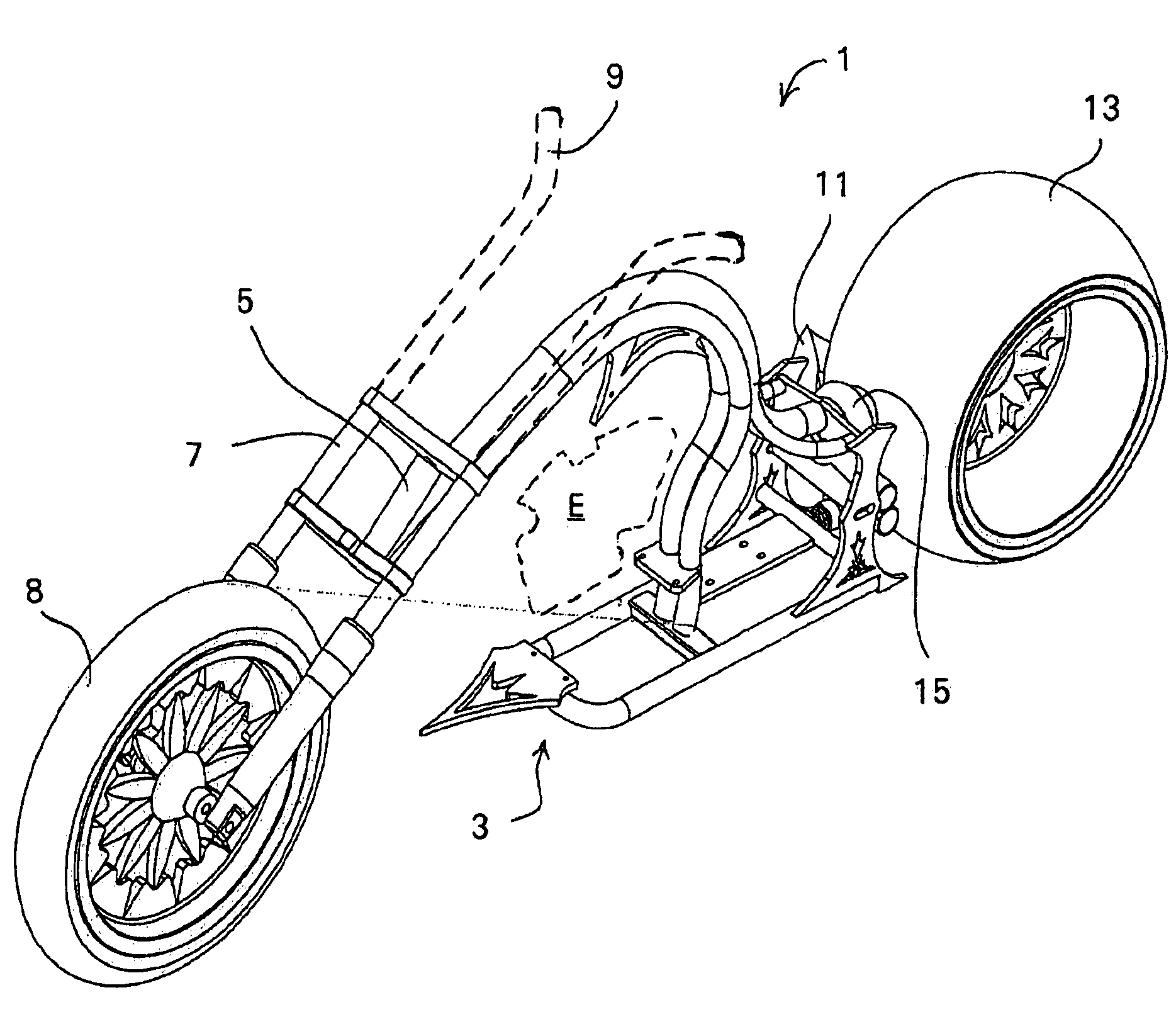
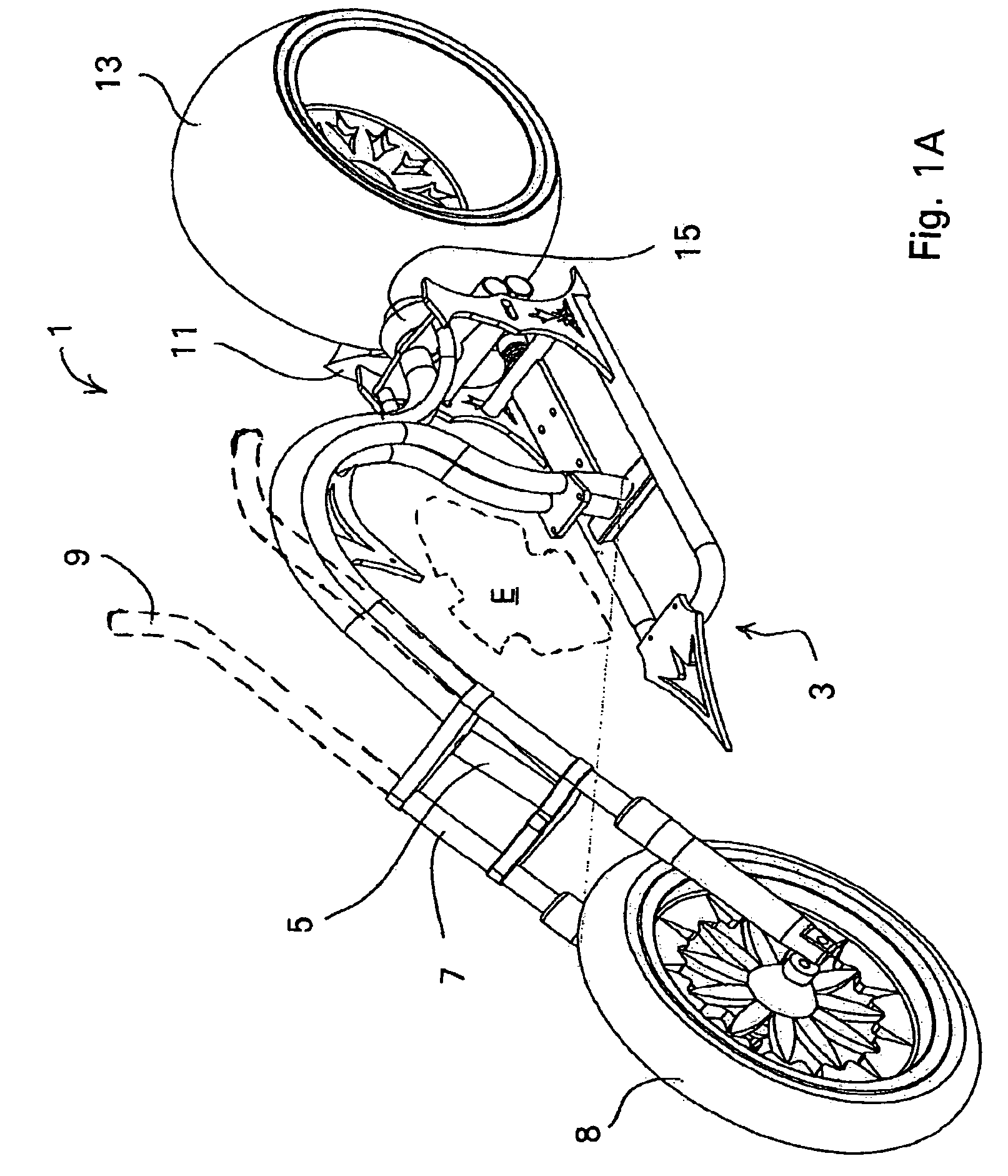
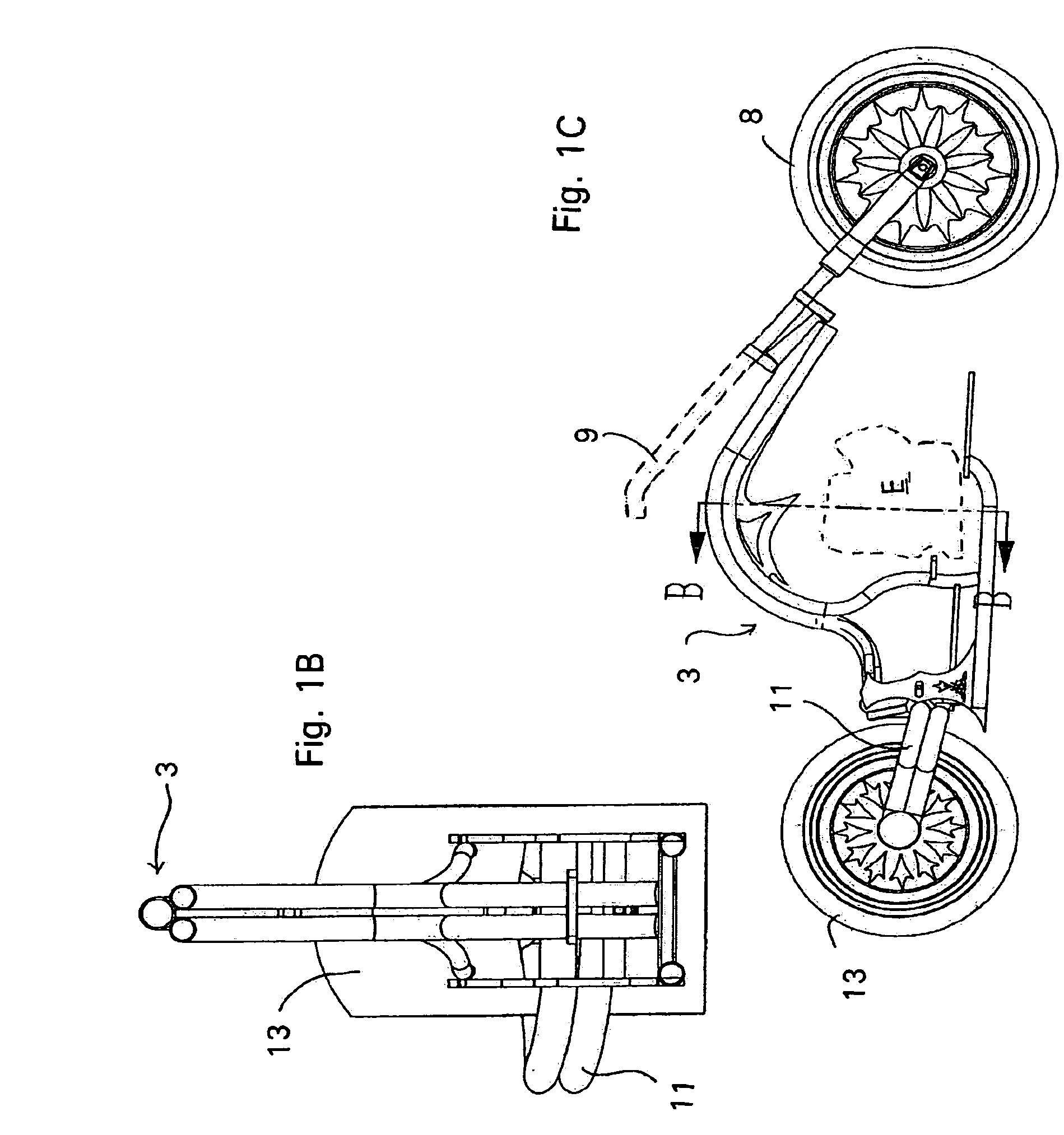
[0033]Referring now in detail to the drawings and initially to FIGS. 1A-C, a motorcycle constructed in accordance with an embodiment of the invention is identified generally by the reference numeral 1. The motorcycle 1 is designed primarily for on-road type use. Although the invention is described in conjunction with a motorcycle for such utilization, it is to be understood that certain facets of the invention can be employed in conjunction with motorcycles used for other purposes, for example off-road riding. However, the invention has particular utility in conjunction with on-road motorcycles.

[0034]By way of a general introduction, the motorcycle 1 includes a frame assembly 3 which is of the welded up, fabricated type. The frame assembly 3 includes a head tube 5 that journals a front fork assembly 7 for steering movement. A front wheel 8 is rotatably attached at the lower end of the front fork 7 by means which may include a suspension system of a known type. A handlebar assembly 9...


PUM


Abstract

A motorcycle frame assembly having a cantilevered, open loop motorcycle frame assembly that achieves a desirable balance between frame strength and rigidity in a lateral and a vertical direction without the necessity of a conventional down tube. The frame assembly utilizes a top tube supported by a top tube support aligned parallel and concentric with at least a portion of the top tube from a connection point with the head tube. The top tube and support being the sole support for the head tube so that a down tube is not necessary.

Description

FIELD OF THE INVENTION[0001]The present invention relates generally to motorcycle frame assemblies and, more particularly, to a cantilevered, open loop motorcycle frame assembly that achieves a desirable balance between frame strength and rigidity in a lateral and a vertical direction without the necessity of a conventional down tube.BACKGROUND OF THE INVENTION[0002]As is well known, motorcycles are generally built upon and around a frame assembly that is made up of a plurality of individual tubes welded together. The typical frame construction includes a head pipe at a front end of the frame, which desirably supports the front wheel via a front fork assembly which is steerable by an attached handle bar(s). A main tube, or tubes, typically extend generally rearwardly from the head pipe and may bend downward over a rear portion of an engine that is positioned generally below the main tube.[0003]In addition, one or more down tubes are typically affixed at their forward ends to the hea...

Claims


Application Information

Patent Timeline
Patent Type & Authority Patents(United States)
IPC IPC(8): B62D61/02
CPCB62K11/06B62K19/06
Inventor PLOURDE, SCOTT
Owner PLOURDE SCOTT
Why Eureka
Try Eureka