
Tool for installing electrical boxes

a technology for installing tools and electrical boxes, which is applied in the direction of electrical apparatus casings/cabinets/drawers, coupling device connections, instruments, etc., can solve the problems of relative accuracy, incorrect positioning of electrical boxes, and the inability to provide electrical boxes at uniform heights from the floor surface, so as to facilitate the alignment of mounting fixtures

Inactive Publication Date: 2010-02-09
MURPHY ROBERT
View PDF18 Cites 5 Cited by
  • Summary
  • Abstract
  • Description
  • Claims
  • Application Information

AI Technical Summary

Benefits of technology

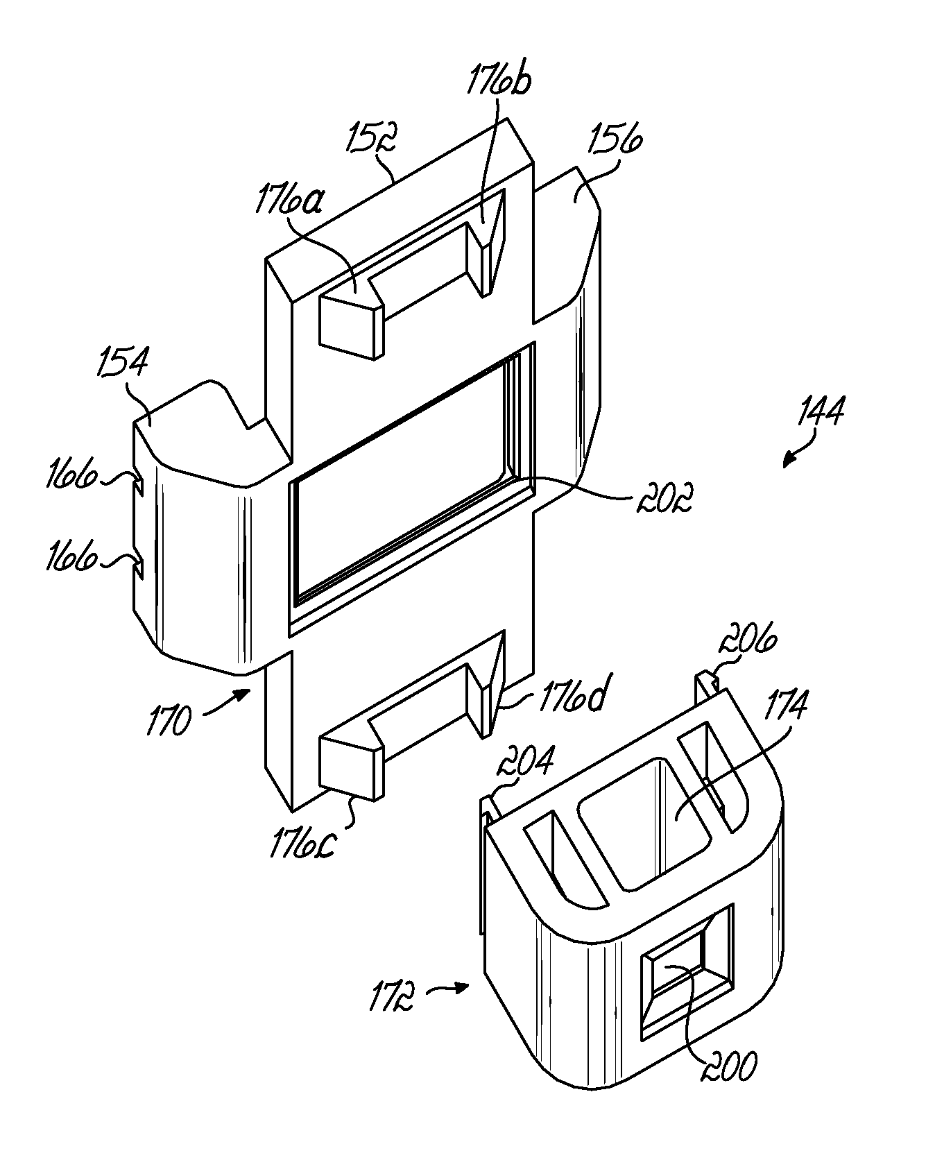
"The present invention is a tool for installing electrical boxes on framing studs in building construction. The tool includes an elongate staff with gradations for measuring distances, and a mounting fixture that can hold an electrical box and also engage with a framing stud to position the electrical box at a desired height. The mounting fixture has two planar surfaces that define the depth of the mounting. The tool also includes detents that help align the mounting fixture with the staff's gradations. The technical effects of this invention include improved accuracy in positioning electrical boxes, simplified installation process, and reduced labor costs."

Problems solved by technology

This procedure is relatively inaccurate and frequently results in incorrect positioning of electrical boxes.
When errors occur, the wall panels will not be flush with the edges of the electrical boxes, or the electrical boxes will not be provided at uniform heights from the floor surface.
Correction of these errors results in inconvenience and delay, and rework of improperly installed electrical boxes often detracts from the appearance of the finished wall surface.
While various devices have been proposed to facilitate installing electrical boxes to framing studs, these prior devices are generally not adapted to accommodate the wide variety of electrical boxes used in building construction.

Method used


Image

  • Tool for installing electrical boxes
  • Tool for installing electrical boxes
  • Tool for installing electrical boxes

Examples


Embodiment Construction

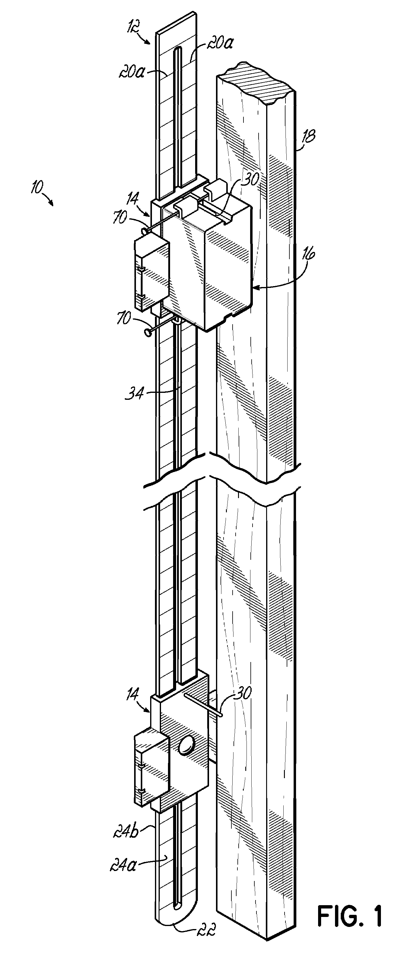
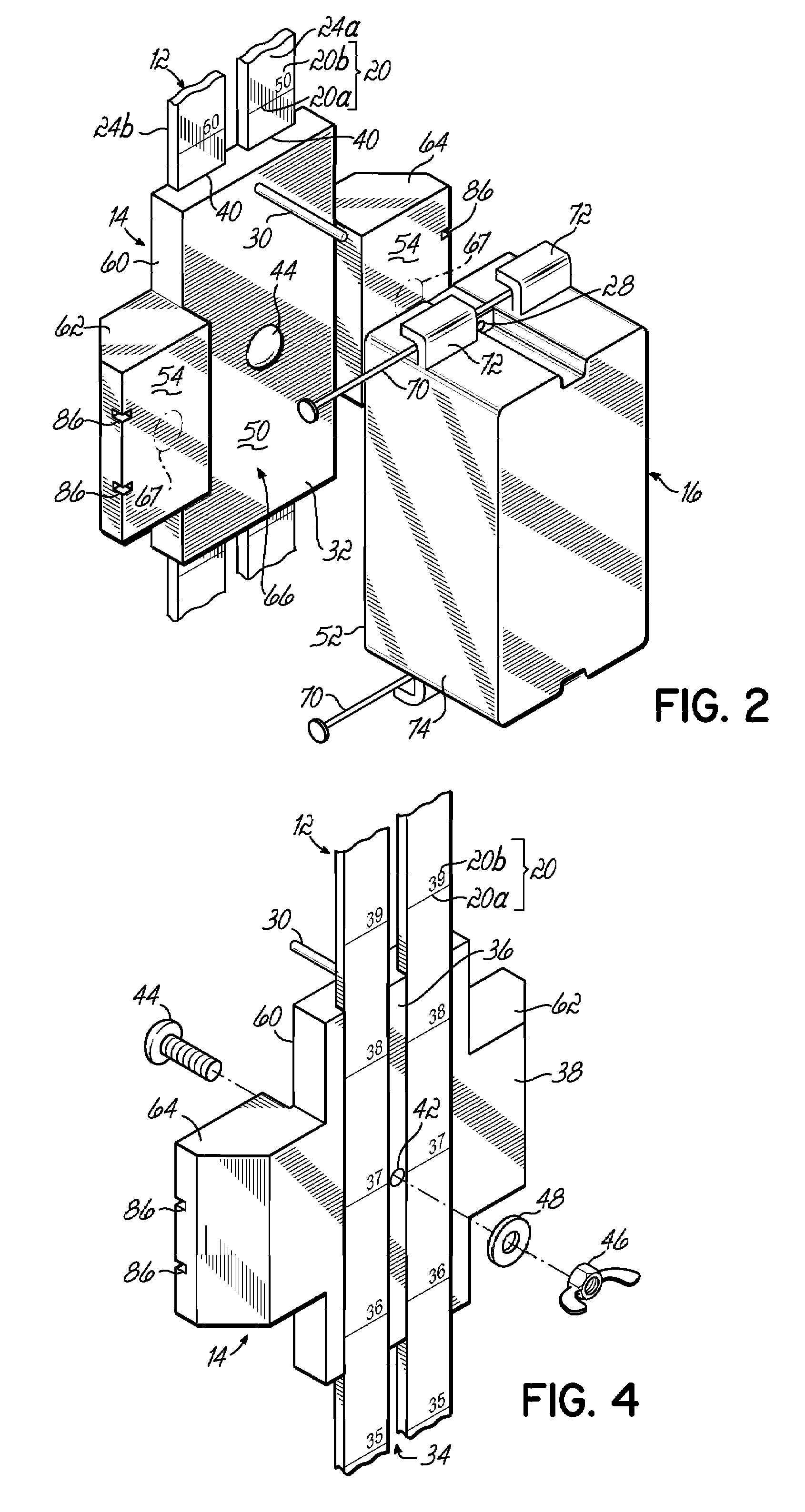
[0038]FIGS. 1-4 depict an exemplary tool 10 for installing electrical boxes, in accordance with the principles of the present invention. The tool 10 includes an elongate staff, or ruler, 12 supporting one or more electrical box mounting fixtures 14 thereon. The electrical box mounting fixtures 14 are slidably adjustable along the length of the staff 12 to desired positions for mounting the electrical boxes 16 to a framing stud 18 of a building. Graduations 20 are provided on the staff 12 to define various distances from a lower end 22 of the staff 12 to facilitate locating the electrical boxes 16 at desired heights above a floor surface. The graduations 20 may comprise hash marks 20a, reference numerals 20b corresponding to distances from the lower end 22 of the staff 12, or various other indicia. In one embodiment, graduations 20 are provided on opposite sides 24a, 24b of the staff 12. The graduations 20 on one side 24a of the staff 12 may be provided in a different unit of measure...


PUM


Abstract

A tool for installing various configurations of electrical boxes to framing studs during building construction includes a staff having graduations indicating distances from an end of the staff. A mounting fixture is slidably disposed on the staff and can be secured at a desired position along the length of the staff corresponding to a desired installation height for the electrical boxes. The mounting fixture may include pins for engaging apertures on an electrical box, and magnets for magnetically engaging metal electrical boxes, to help retain the electrical boxes on the mounting fixture during installation.

Description

[0001]This Application is a continuation-in-part of U.S. patent application Ser. No. 11 / 420,925, filed May 30, 2006 (pending), the disclosure of which is incorporated by reference in its entirety.FIELD OF THE INVENTION[0002]The present invention relates generally to building construction, and more particularly to a device to facilitate installing electrical boxes on wooden and metal framing studs.BACKGROUND OF THE INVENTION[0003]Residential and commercial buildings are typically constructed using wooden or metal framing studs. The framing studs support wall panels made from drywall or other materials that are used to finish interior rooms in buildings. During construction, electrical boxes for housing switches, outlets, and various electrical controls are typically mounted to the framing studs prior to installation of the wall panels. The electrical boxes are generally installed at uniform heights above a floor surface, and must be positioned to allow installation of the wall panels...

Claims


Application Information

Patent Timeline
Patent Type & Authority Patents(United States)
IPC IPC(8): H01H9/02
CPCH02G3/00H02G3/123Y10S248/906H02G2200/30
Inventor MURPHY, ROBERT
Owner MURPHY ROBERT
Learn More