
Magnetic connector

a magnetic connector and connector technology, applied in the direction of incorrect coupling prevention, coupling device connection, electrical apparatus, etc., can solve the problems of inability to maintain satisfactory electrical contact between the electrical contacts in the connector is sometimes decoupled inadvertently, and the electrical contact between the plug and the receptacle may not be maintained

Inactive Publication Date: 2010-02-09
VINCI BRANDS LLC
View PDF4 Cites 137 Cited by
  • Summary
  • Abstract
  • Description
  • Claims
  • Application Information

AI Technical Summary

Benefits of technology

The present invention is a connector that uses magnets to ensure the plug and receptacle are properly aligned. The magnets have a polarity that naturally attracts them, and the faces of the plug and receptacle have matching surfaces that only allow them to connect when the plug is in the correct position. The connection is secure, and the ground contacts on the plug and receptacle are connected before any other electrical contacts are connected. The technical effect of this invention is to provide a reliable and secure connection between the plug and receptacle, even in situations where they may be exposed to external forces or vibrations.

Problems solved by technology

The technical problem addressed in this patent text is the inadvertent decoupling of electrical connectors, which can result in damage to connected electronic devices and even surge currents that may damage the electronics associated with the device. The solution needed is an improved connector that prevents accidental decoupling and maintains satisfactory electrical contact between the electrical contacts in the plug and receptacle.

Method used


Image

  • Magnetic connector
  • Magnetic connector
  • Magnetic connector

Examples


Embodiment Construction

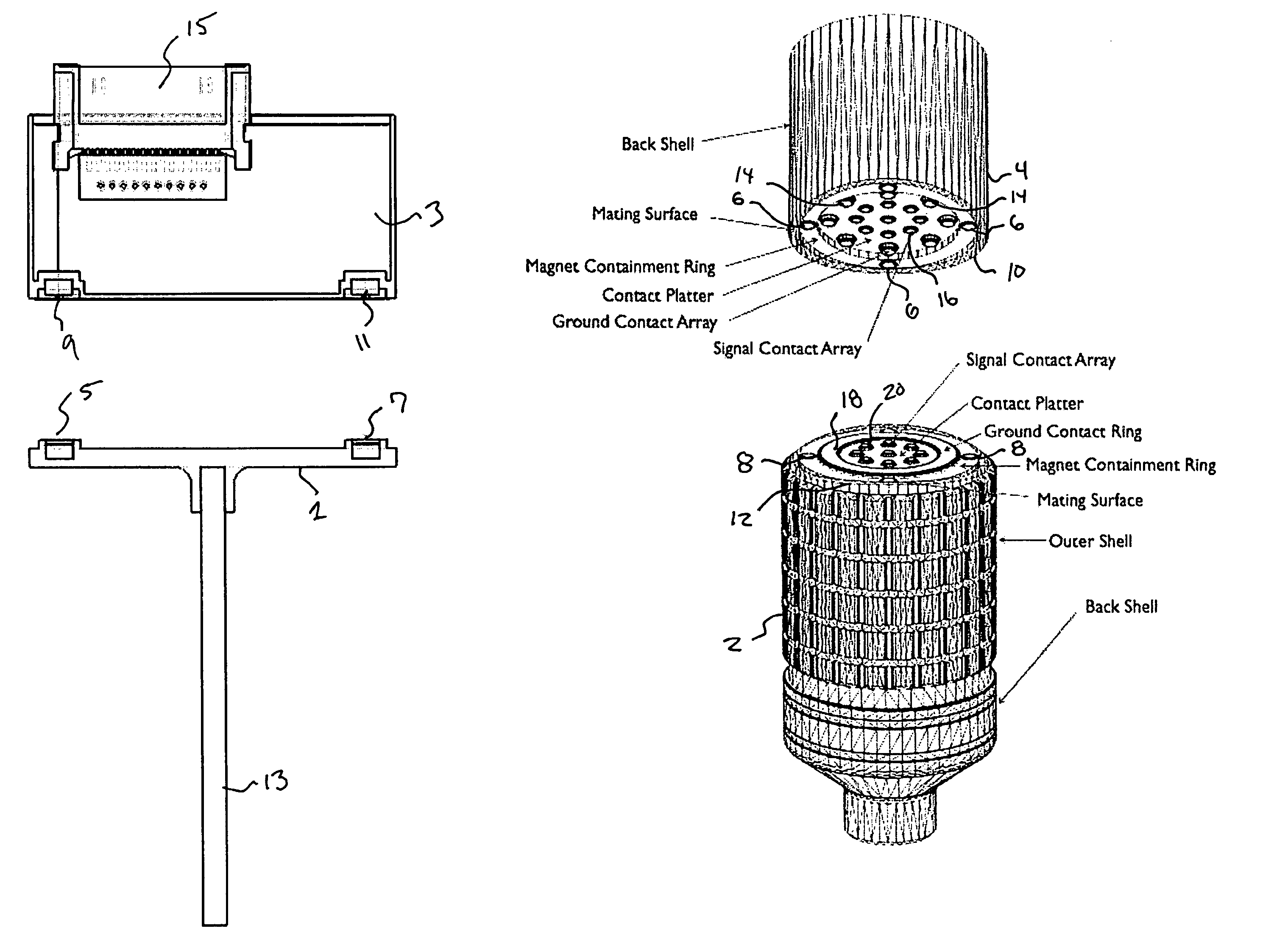
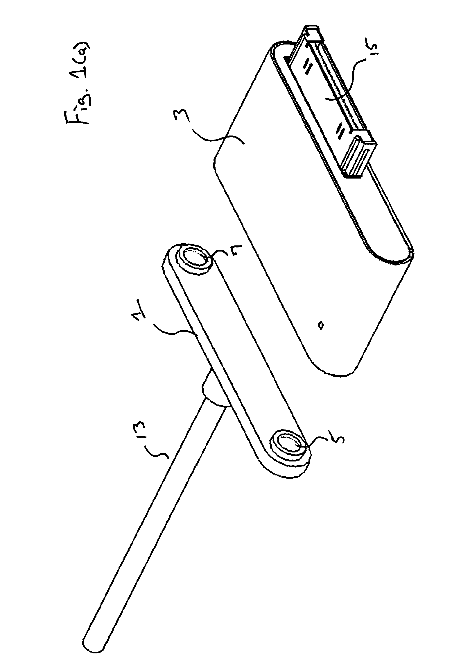
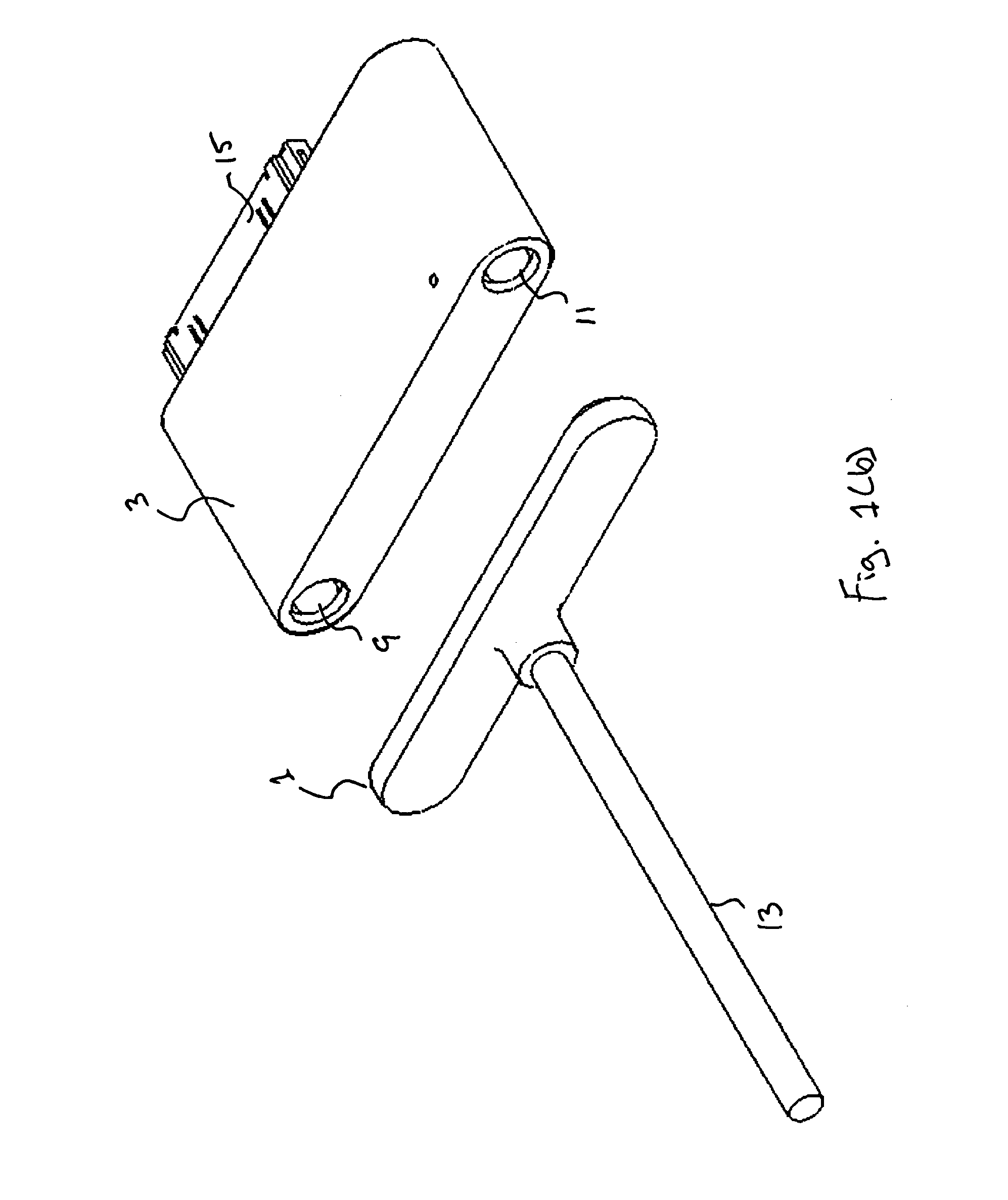
[0015]Referring now to FIGS. 1(a-c), a pair of mating connectors constructed in accordance with an embodiment of the present invention is shown. Each of the connector ends 1 and 3 has a pair of magnets 5, 7, 9 and 11, preferably Neodymium magnets, positioned thereon. The magnets are constructed such that the polarity of the magnets is aligned such that magnetic attraction between the magnets draws and holds the connector ends 1 and 3 together when the connector ends are properly aligned. The magnets 9 and 11 on one connector end 3 are recessed while the magnets 5 and 7 on the other end 1 protrude to provide a limited physical connection as well as a magnetic connection when the connector ends 1 and 3 are properly aligned and coupled. In addition, in the embodiments of FIGS. 1(a)-(c), the magnets are electrically connected to conductors in the cable 13 and connector 15. These electrical connections allow electrical signals and power to be transferred from a device coupled to the conn...


PUM


Abstract

A connector uses complimentary magnetic arrays and mating surfaces on its plug and receptacle to facilitate connection and disconnection of the connector. The plug includes a magnetic array wherein the polarity of the magnets facing the receptacle when the plug and receptacle are connected is selected such that they can only be mated with a complimentary magnetic array on the receptacle when the plug has a desired orientation with respect to the receptacle. The plug and receptacle also have mechanical mating surfaces on their circumference that are shaped such that the plug and the receptacle can only be connected with the desired orientation. The plug can be separated from the receptacle by rotating the plug with respect to the receptacle such that the mechanical mating surfaces break the magnetic connection between the complimentary magnetic arrays.

Description


Claims


Application Information

Patent Timeline
Owner VINCI BRANDS LLC
Learn More