
Modified boiler wall tube tool

a technology for boiler tubes and tools, which is applied in the field of modified boiler wall tube tools, can solve the problems that the tools disclosed in the above-mentioned patents are not particularly adapted for use with boiler tubes, and achieve the effect of expanding the versatility of the first clamp member

Inactive Publication Date: 2010-02-09
MCCLURE MARK W
View PDF25 Cites 12 Cited by
  • Summary
  • Abstract
  • Description
  • Claims
  • Application Information

AI Technical Summary

Benefits of technology

"The invention is a boiler wall tube tool that allows for the secure and easy attachment of boiler wall tubes. The tool includes two clamps with different radii that can be reversed to accommodate tubes of different sizes. The tool also has slots for securely attaching it to the boiler wall tubes using a threaded bolt and a free floating nut. The tool is designed to improve the efficiency and versatility of the attachment process."

Problems solved by technology

The tools disclosed in the above-mentioned patents are not especially adapted for use with boiler tubes forming a boiler wall.

Method used


Image

  • Modified boiler wall tube tool
  • Modified boiler wall tube tool
  • Modified boiler wall tube tool

Examples


Embodiment Construction

[0025]The detailed description below is intended to provide examples of the invention through multiple embodiments disclosed herein. It is to be understood that a variety of other arrangements are also possible without departing from the spirit and scope of the invention as described and claimed.

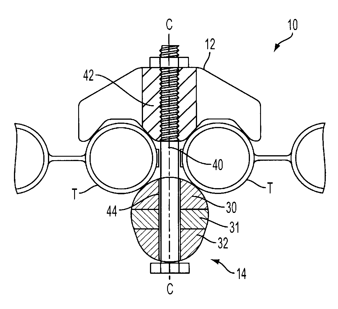
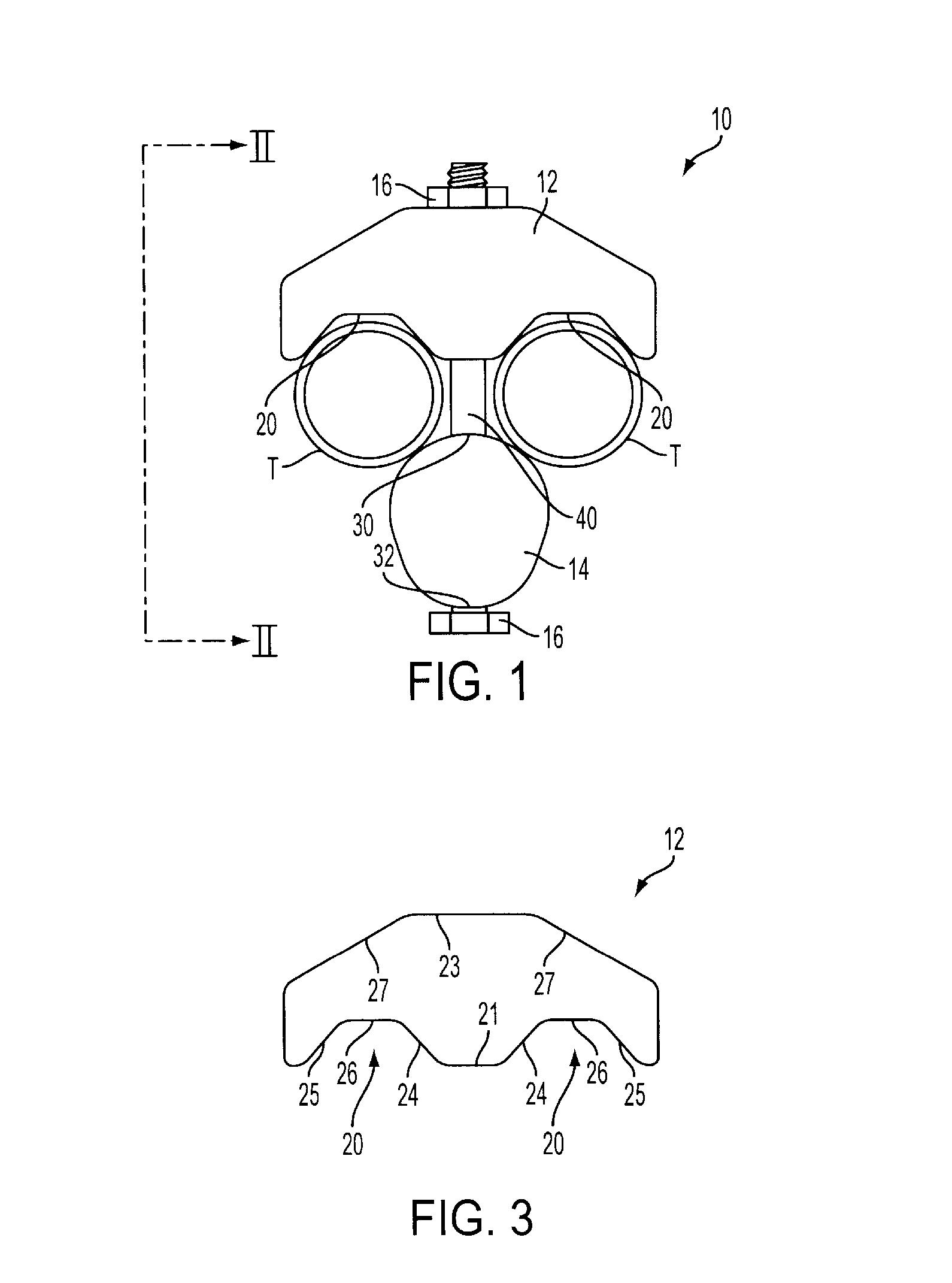
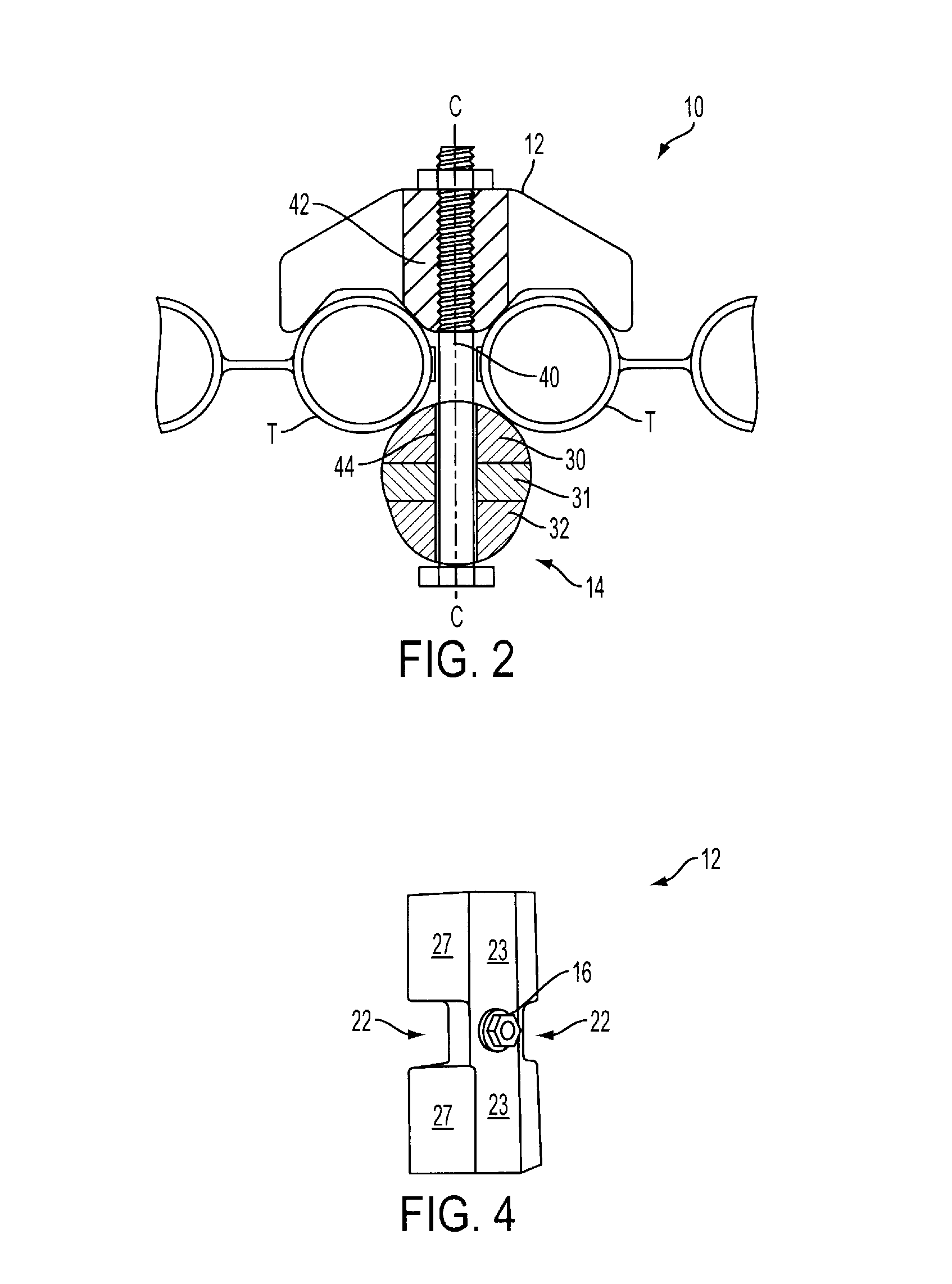
[0026]Referring now to FIG. 1 through FIG. 4, a boiler wall tube tool 10 (hereinafter “tool”) is depicted in accordance with one embodiment of the invention. The tool 10 generally comprises a first clamp member 12, a second clamp member 14 and means for securing the first clamp member 12 and the second clamp member to the boiler wall tubes “T”. In particular, the tool 10 comprises a first clamp member 12 having a pair of recesses 20 engaging a pair of boiler wall tubes “T” and a pair of recesses 22 formed in the sides of the first clamp member 12 providing access to the periphery of the boiler wall tubes “T”. The tool 10 also includes a second clamp member 14 having a first radius 30 opposit...


PUM

PropertyMeasurementUnit
radiusaaaaaaaaaa
widthaaaaaaaaaa
dimensionsaaaaaaaaaa

Abstract

A boiler wall tube tool has a first clamp member positioned about one side of the boiler wall and a second clamp member positioned about the opposite side of the boiler wall. The first clamp member has recess or recesses, each recess receiving one of the tubes therein. The second clamp member has a radius or radiuses abutting against the opposite side of a tube or the tubes. The first clamp member and the second clamp member are coupled to one another about the tube or tubes through slots formed in the first clamp member and the second clamp member.

Description

RELATED U.S. APPLICATION DATA[0001]Not applicable.FIELD OF THE INVENTION[0002]This invention relates generally to a tool for use in securing the ends of a boiler tubes along a boiler wall in aligned relation so that the ends of the tubes may be joined via welding. Specifically, this invention relates to a modified boiler wall tube tool in which boiler tubes in the form of a wall can be clampingly secured to retain adjacent ends of the boiler tubes forming the wall in aligned relation when connection the ends of the boiler wall tubes by welding.BACKGROUND OF THE INVENTION[0003]Tools for clamping and aligning boiler tubes when connecting the ends of the boiler tubes by welding are known as disclosed in U.S. Pat. Nos. 4,493,139, 4,579,272 and 4,722,468. The devices disclosed in the above-mentioned patents include structures for securing boiler tube ends in aligned and adjacent relation and function effectively when the boiler tubes are in spaced relation. However, in boiler wall tubes,...

Claims


Application Information

Patent Timeline
Patent Type & Authority Patents(United States)
IPC IPC(8): F16L3/00
CPCB23K31/02B25B5/003B25B5/147B23K2201/06B23K2201/14Y10T29/53917Y10T29/53796Y10T29/53913Y10T29/54B23K2101/06B23K2101/14
Inventor MCCLURE, MARK W.
Owner MCCLURE MARK W
Learn More