
Transporting crate for picture frames

a transporting crate and picture frame technology, applied in the direction of containers, tray containers, packaged goods, etc., can solve the problems of not being suitable for transporting crates of different dimensions, and achieve the effect of convenient cutting and easy cutting

Active Publication Date: 2010-01-12
HASENKAMP INT TRANSPORTE
View PDF17 Cites 33 Cited by
  • Summary
  • Abstract
  • Description
  • Claims
  • Application Information

AI Technical Summary

Benefits of technology

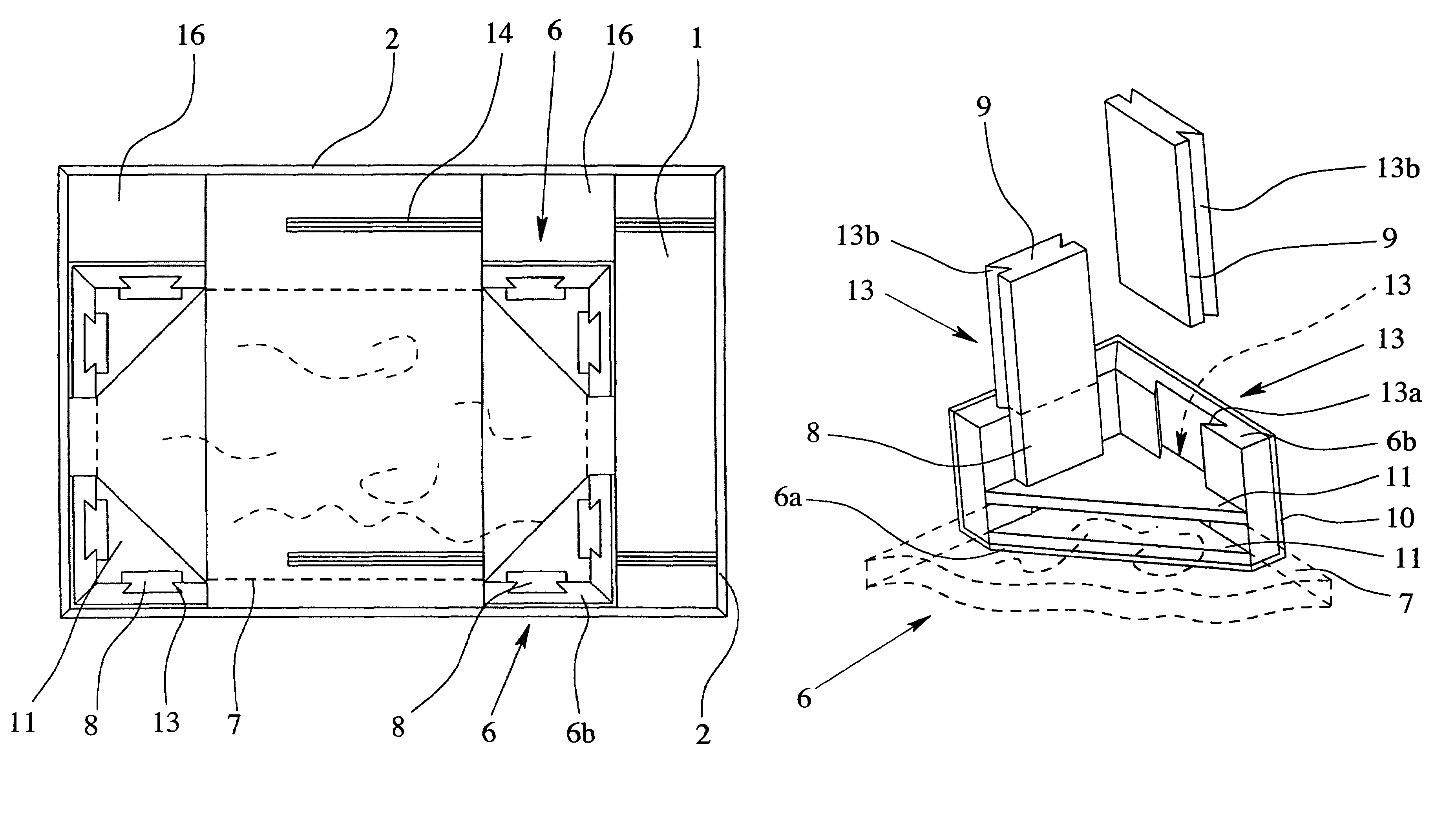
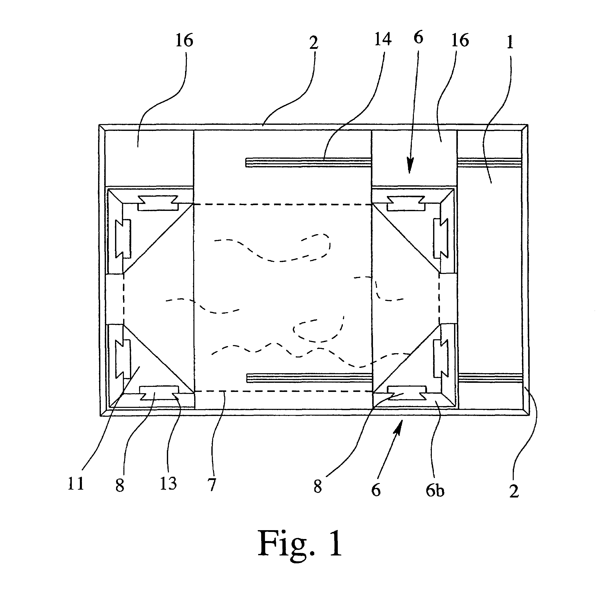
[0021]The solution which is preferred according to the invention for adapting the length of the actual heightwise spacer to the thickness of the picture frame which has been placed in position is based on the fact that the “supply” of heightwise spacers is provided in the form of a continuous, longer rod or strip, possibly also wound up in roll form, made of lightweight, padding, foamed plastic material or some other material which is particularly easy to cut. For example, using a rod made of balsawood would also advantageously be possible in principle. The essential factor is for the material to be one which is easy to cut, using straightforward means, on site.
[0022]The transporting crate which is proposed according to the invention makes it possible for the specific picture frame to be positioned in the frame-fastening elements and then for the heightwise spacers for the individual frame-fastening elements to be cut to the length appropriate for the spacing which remains in the height direction up to the inside of the closed cover.

Problems solved by technology

A further disadvantage of the transporting crate explained above is that, in terms of all its dimensions, it is suitable basically just for a quite specific picture frame.
The disadvantages which have been explained above in respect of the transporting crate not being suitable for picture frames of different dimensions have already been recognized in the prior art.

Method used


Image

  • Transporting crate for picture frames
  • Transporting crate for picture frames
  • Transporting crate for picture frames

Examples


Embodiment Construction

[0045]In order to explain the basic construction of a transporting crate for picture frames or the like, reference will be made first of all to FIG. 7, which shows the prior art. Indeed, the basic construction of FIG. 7 also applies to the present transporting crate according to the invention.

[0046]The transporting crate for picture frames or the like which is illustrated in perspective in FIG. 7 has, in the first instance, a base 1 which in this case consists of plywood or laminated wood and defines a length direction and a width direction. Fixed to the base 1 are a plurality of side walls 2 which define a height direction, in this case four side walls 2, which are arranged in a rectangle, and likewise consist of plywood or laminated wood. Additional wooden struts 3 can be seen on the side walls 2. Wood is the most commonly used material for such a transporting crate, although it would, of course, also be possible in principle, to use aluminum or some other metal or a corresponding...


PUM


Abstract

In the case of the picture-frame transporting crate according to the invention, a spacing which remains in the height direction between the closed cover (4) and the top side of a picture frame (7) which has been placed in position, or of a padding plate which covers the top side of the picture frame, is filled by means of a heightwise spacer (8) which is coordinated precisely, in terms of length, with this spacing. For this purpose, either a heightwise spacer (8) of appropriate length is selected from a supply or the appropriate heightwise spacer (8) is produced on site by virtue of the appropriate length being cut off precisely from a longer strip or a longer rod.

Description

CROSS-REFERENCE TO RELATED APPLICATION[0001]This application claims priority to German Application No. 20 2005 011 897.4, filed Jul. 26, 2005.FIELD OF THE INVENTION[0002]The invention relates to a transporting crate for picture frames. The teaching of the present invention is explained hereinbelow with reference to the preferred application area for picture frames. It should always be kept in mind, however, that the teaching of the invention can also be applied to other corresponding sheet-like objets d'art such as wooden panels, altarpieces or reliefs, but also for frameless pictures, if these are underpinned by additional supporting plates or panels.[0003]The teaching of the present invention also concerns a method of positioning and fixing a picture frame in a transporting crate of the type in question.BACKGROUND OF THE INVENTION[0004]Transporting crates are usually used for transporting pictures in picture frames. These crates are usually produced from wood and contain the pictu...

Claims


Application Information

Patent Timeline
Patent Type & Authority Patents(United States)
IPC IPC(8): B65D81/02B65D85/00B65D85/48B65D25/10B65D81/05B65D81/107B65D81/127
CPCB65D81/053B65D81/1275B65D81/057
Inventor HOHNE, UWEPUTZ, UDOBISSOT, MICHAEL
Owner HASENKAMP INT TRANSPORTE
Learn More