
Predictive video device system

a video device and video technology, applied in the field of prediction and telepresence systems, can solve the problems of user difficulty in adjusting to camera motion, the actual position of the camera to overshoot the desired position, and the control of the remote positioning can become even more complex

Inactive Publication Date: 2010-01-05
HEWLETT PACKARD DEV CO LP
View PDF10 Cites 29 Cited by
  • Summary
  • Abstract
  • Description
  • Claims
  • Application Information

AI Technical Summary

Benefits of technology

[0013]The present invention provides a predictive device system including providing a first device motion control input; determining a desired first device motion using the first device motion control input; providing actual first device motion using the first device motion control input; determining motion inherent in a received sign

Problems solved by technology

In video communication systems where moveable or zoomable video cameras at a remote location are under control of a local user, feedback delays can cause difficulties for users in adjusting to camera motion at the remote location.
However, additional delays in the control loop can cause the actual position of the camera to overshoot the desired position of the camera.
As more complex systems evolve, control of the remote positioning can become even more complex.
However, delays of several seconds can occur between user commands such as controlling speed via a pistol grip and the resulting change in video presentation for the user.

Method used


Image

  • Predictive video device system
  • Predictive video device system
  • Predictive video device system

Examples


Embodiment Construction

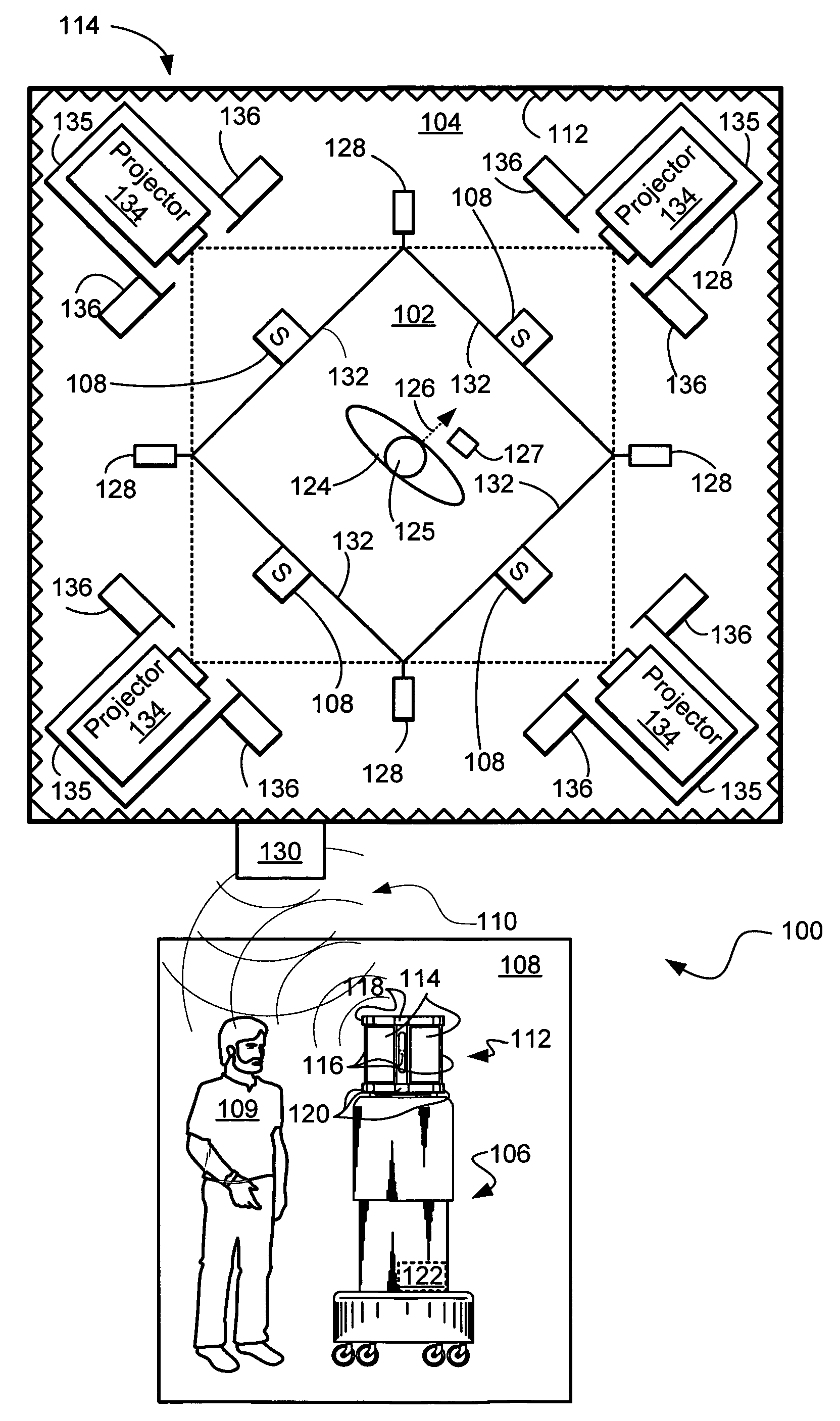
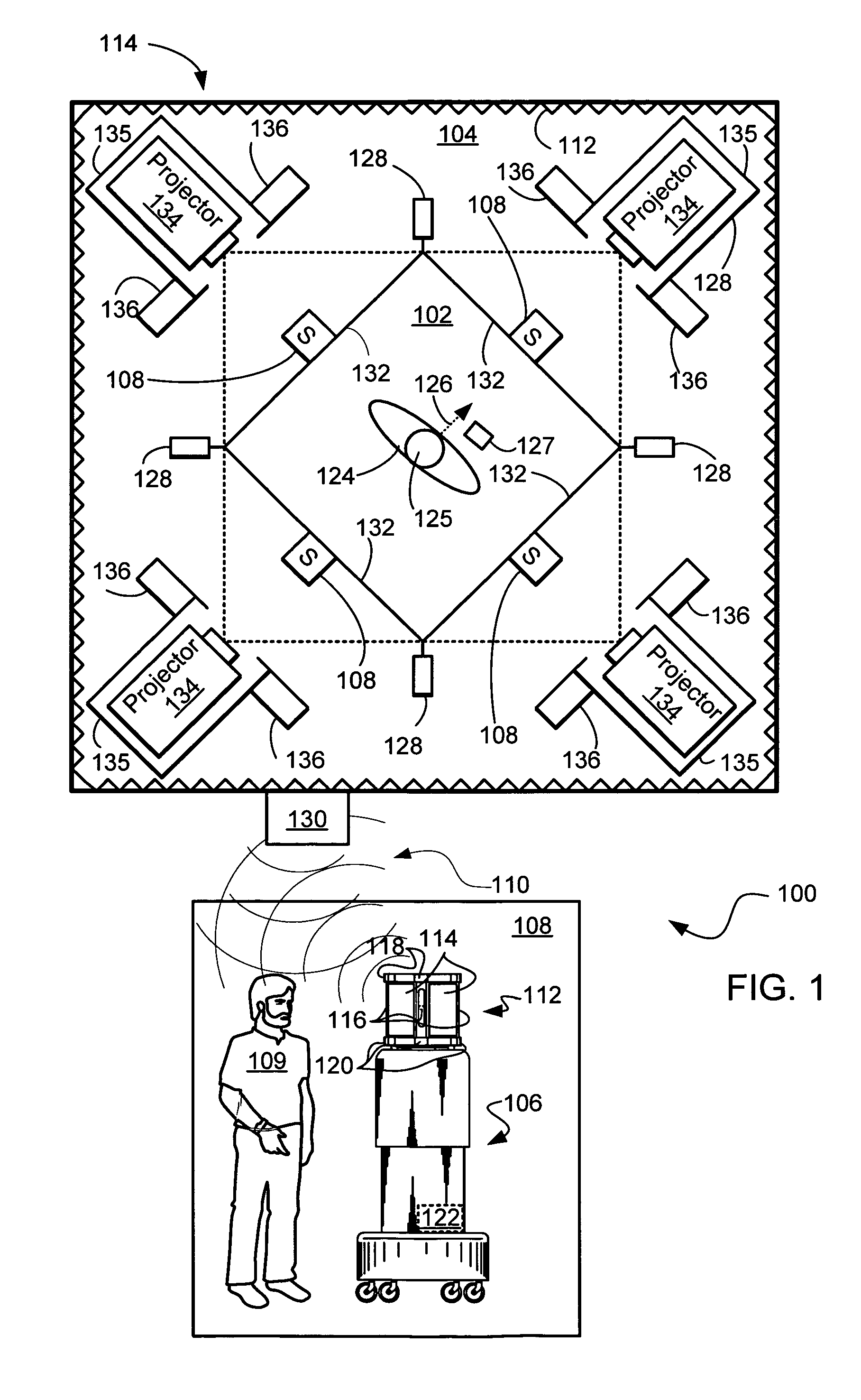
[0021]The present invention relates to a Mutually-Immersive Mobile Telepresence (E-Travel) System. A user sits in a room showing the remote meeting location and a robot device is located at a remote meeting location. Video and audio are transmitted between the display and the robot device so that the user has the feeling of being present at the remote location by seeing it in a surround view, and the people or meeting participants at the remote location have the feeling that the user is present by panels showing images of the head of the user; i.e., the feeling of telepresence. The robot device may have a humanoid as well as a non-humanoid shape, and is referred to as a “surrogate”.

[0022]For example, the user sits or stands inside a display cube, with rear-projection surfaces on the front, back, sides, and optionally the ceiling showing images of the surrogate's location. Since the goal is to be mutually immersive, full-size live color video images of the user centered on the user's...


PUM


Abstract

A predictive device system includes a first device motion control input, determines a desired first device motion using the first device motion control input, and provides actual first device motion using the first device motion control input. The predictive system also determines motion inherent in a received signal using the actual first device motion, determines a difference to be simulated in a second device signal using the desired first device motion and the motion inherent in the received signal, and outputs a predictive signal using the first device motion control input and the difference to be simulated in the second device signal.

Description

BACKGROUND[0001]1. Technical Field[0002]The present invention relates generally to robotics and more specifically to telepresence systems.[0003]2. Background Art[0004]In the past, video camera and audio systems were developed for improving communication among individuals who are separated by distance and / or time. The systems and the process are now referred to as “videoconferencing”. Videoconferencing sought to duplicate, to the maximum extent possible, the full range, level and intensity of interpersonal communication and information sharing which would occur if all the participants of a meeting were “face-to-face” in the same room at the same time.[0005]In addition to spoken words, demonstrative gestures, and behavioral cues, face-to-face contact often involves sitting down, standing up, and moving around to look at objects or people. This combination of spoken words, gestures, visual cues, and physical movement significantly enhances the effectiveness of communication in a variet...

Claims


Application Information

Patent Timeline
IPC IPC(8): H04N5/232G05B15/00G05B19/00G05B19/18G06K9/00
CPCH04N5/232H04N7/144H04N7/147H04N7/15
Inventor JOUPPI, NORMAN PAUL
Owner HEWLETT PACKARD DEV CO LP
Learn More