
Breast pump

a technology of a pump and a stent, which is applied in the field of stents, can solve the problems of high manufacturing cost, large noise, and generally speaking rather complicated mechanisms

Active Publication Date: 2010-01-05
CHIARO TECH LTD
View PDF18 Cites 18 Cited by
  • Summary
  • Abstract
  • Description
  • Claims
  • Application Information

AI Technical Summary

Benefits of technology

"The present invention provides an electric breast pump with a hood for fitting over a user's breast and a chamber connected to the hood through a valve. The pump has a motor and a closure member that can open and close the valve to control the air flow. The closure member is moved by the motor to open or close the valve. Additionally, the invention includes a sensing unit to detect the presence of milk. The technical effects of this invention include improved breast pumping efficiency, comfort, and the ability to detect milk flow."

Problems solved by technology

Such mechanisms are generally speaking rather complicated, and thus costly to manufacture.
In addition, most such mechanisms include gear trains which would generate much noise, especially when the motor is operating at a relatively high speed.
In addition, although a user may, with some existing breast pumps, be able to adjust the pumping cycles, e.g. by varying the number of suction cycles per minute, or adjusting the vacuum level for pumping milk from the user's breast, it is up to the user to decide whether to make such variation or adjustment, and the user may simply have no information on which to decide whether the current pumping rate is suitable or not.
However, as in the case of other adjustable breast pumps discussed above, it is still up to a user to decide whether to change the mode of pumping operation of the breast pump, and a user may not know whether an alternative, and if so which, suction curve should be applied.

Method used


Image

  • Breast pump
  • Breast pump
  • Breast pump

Examples


Embodiment Construction

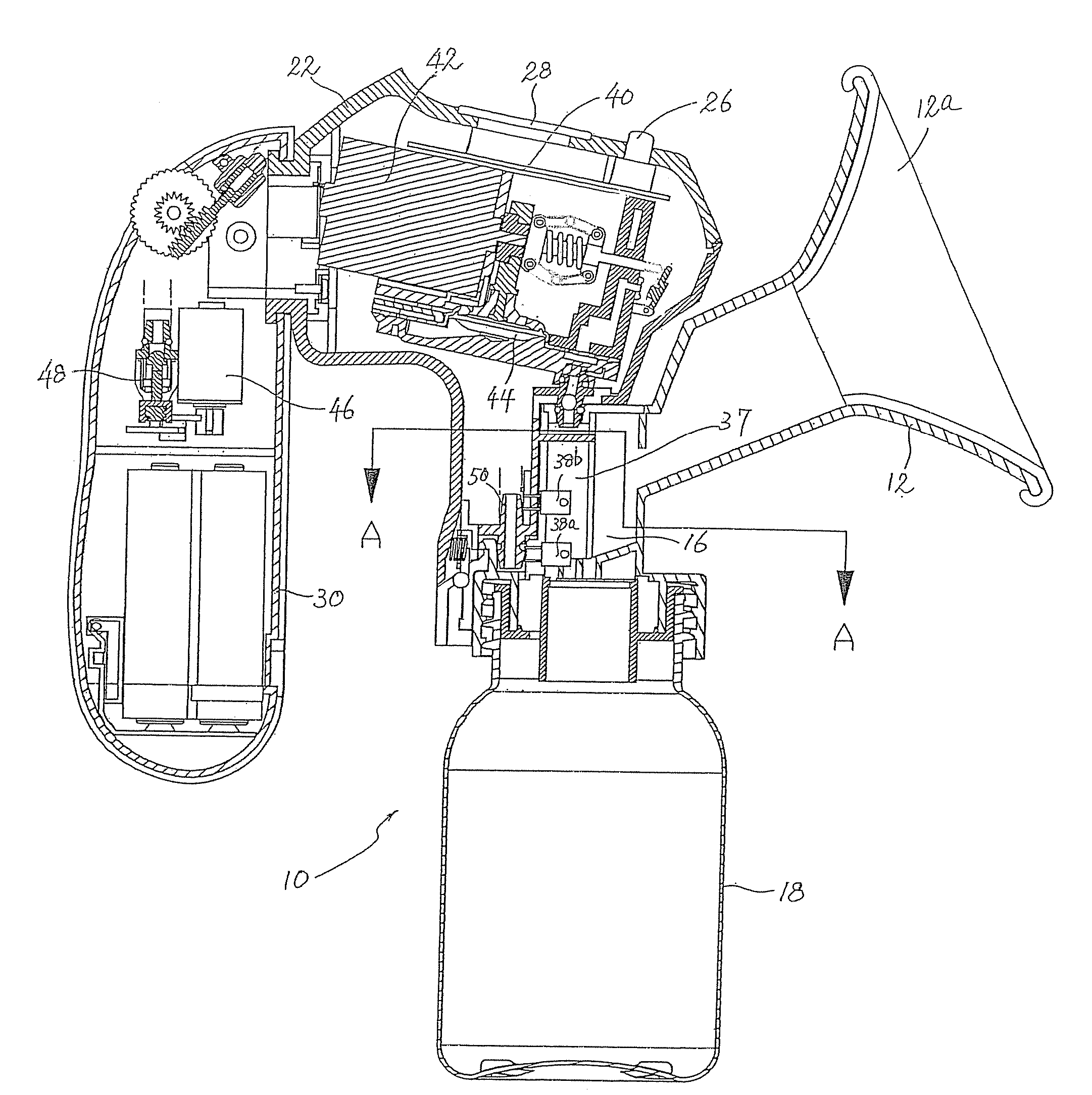
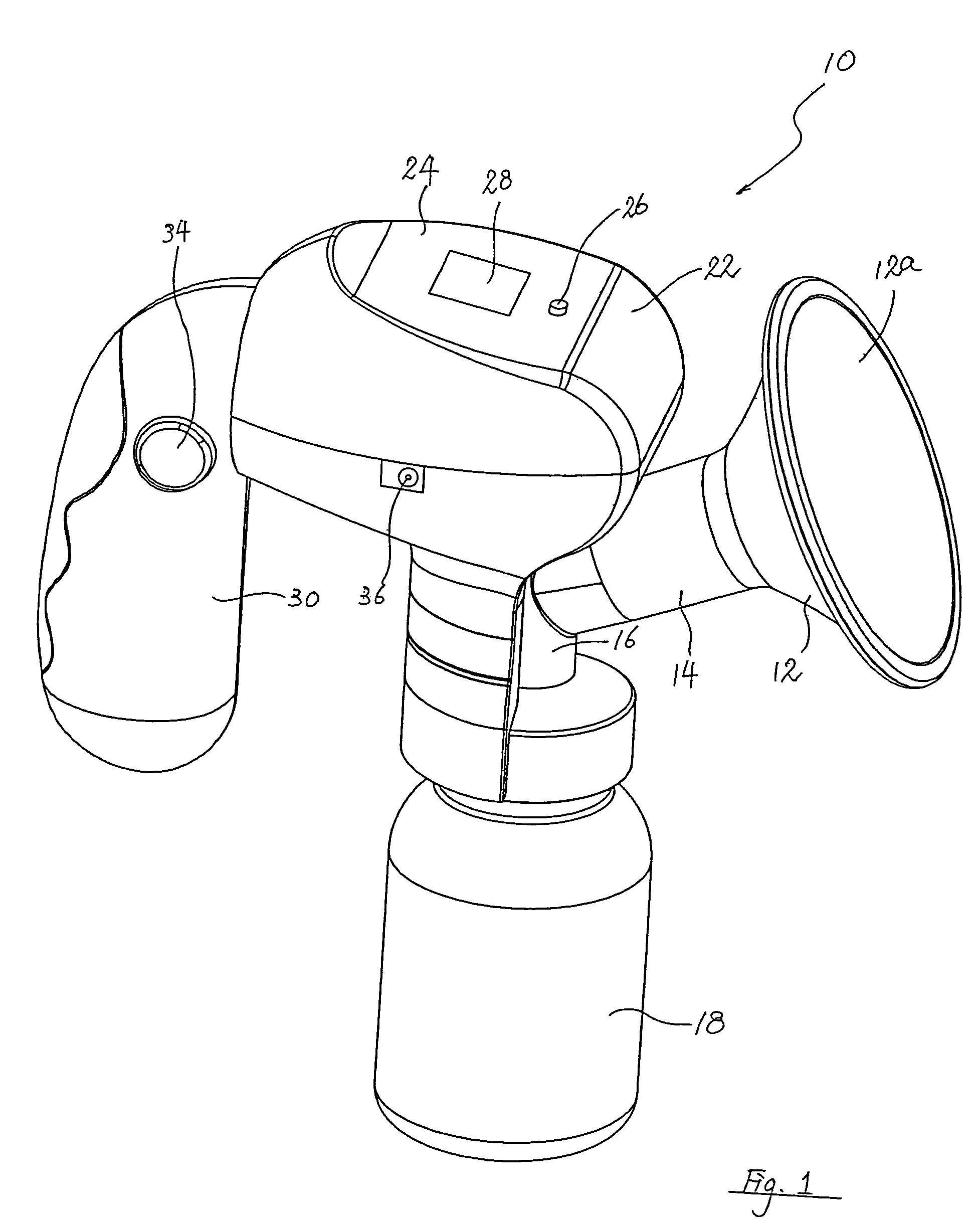
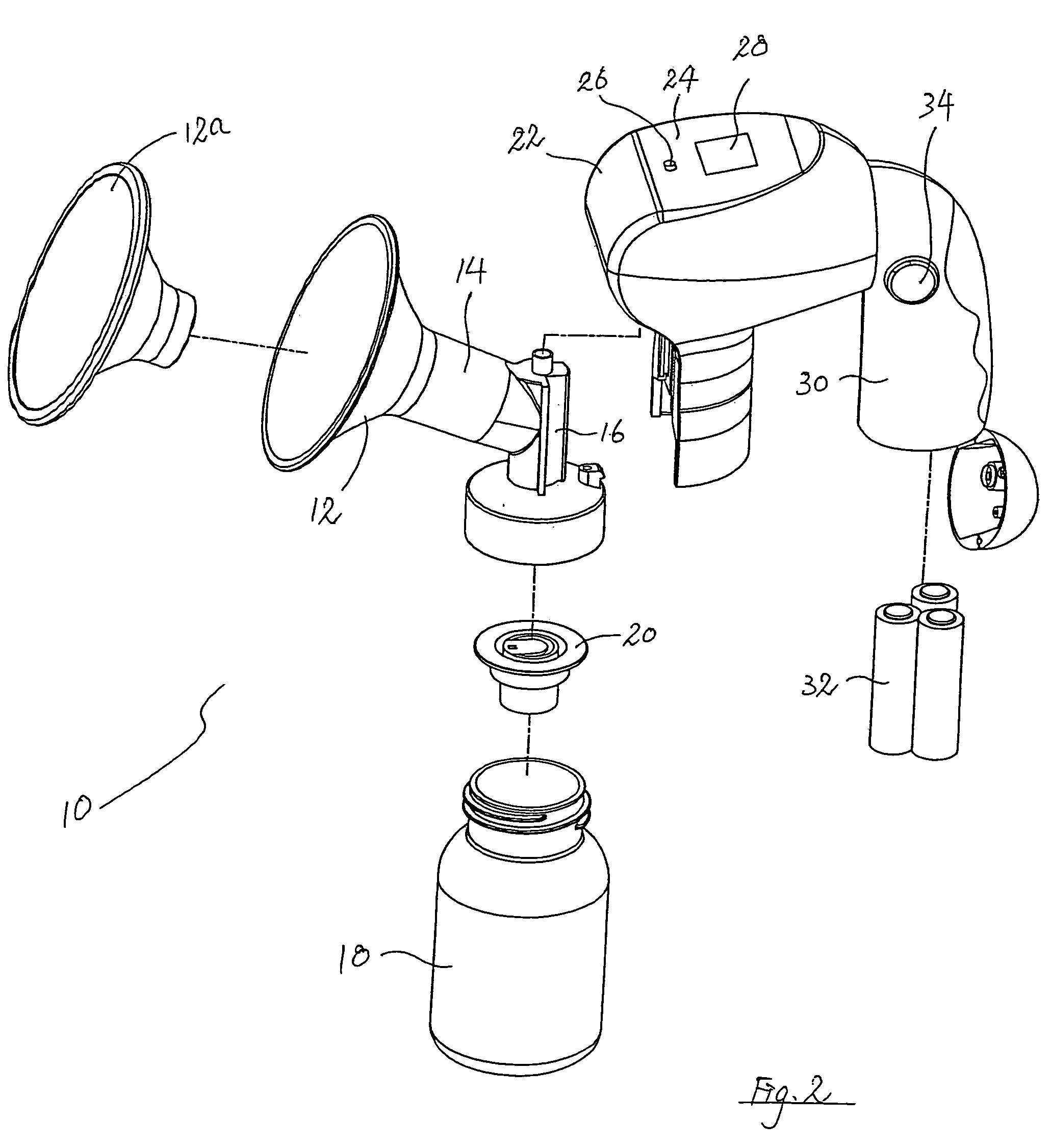
[0024]FIGS. 1 and 2 show an electrically operated breast pump according to a preferred embodiment of the present invention, generally designated as 10. The breast pump 10 has a hood 12 adapted to be fitted over a breast of a user in an essentially gas-tight manner, for pumping milk from the breast. An insert 12a for contacting the user's breast is received within the hood 12. The insert 12a is made of a soft plastic material, e.g. silicone, to provide comfort to the user during use. The hood 12 is in funnel shape and has a tunnel 14 leading to a connector 16, which fluidly communicates with the hood 12, and with a milk-receiving bottle 18 via a valve seat 20, the structure and function of which will be further discussed below.

[0025]The connector 16 is engaged with a head portion 22 which houses most of the operating components of the breast pump 10, as will be clear from the ensuing discussion. On a top surface 24 of the head portion 22 is provided with an ON / OFF button 26 for selec...


PUM


Abstract

An electric breast pump is disclosed as including a hood to be fitted over a breast of a user, a chamber in fluid communication with the hood member via a one-way valve, a pump motor operatively associated with a pump diaphragm movable to draw air from the hood into the chamber via the valve, in which the chamber has an opening and a lid which is operatively associated with the motor, in which the lid is movable between a first position to close the opening and a second position in which the opening is open, and in which the lid is at the first position when the motor is in operation and is at the second position when the motor is not in operation. The breast pump also includes sensors for detecting the passing of milk, and a microcontroller for calculating the rate of flow of milk on the basis of data received from the sensors.

Description

[0001]This invention relates to a breast pump and, in particular, an electrically operated breast pump for drawing milk from a user.BACKGROUND OF THE INVENTION[0002]There are in existence a large number of electrically operated breast pumps, allowing a user, e.g. a mother, to pump milk from her breast. Various pumping mechanisms have been proposed for drawing milk from the mother's breast, including, for example, ones disclosed in U.S. Pat. Nos. 6,045,529 and 6,355,012 issued to Nüesch. Such mechanisms are generally speaking rather complicated, and thus costly to manufacture. In addition, most such mechanisms include gear trains which would generate much noise, especially when the motor is operating at a relatively high speed.[0003]In addition, although a user may, with some existing breast pumps, be able to adjust the pumping cycles, e.g. by varying the number of suction cycles per minute, or adjusting the vacuum level for pumping milk from the user's breast, it is up to the user t...

Claims


Application Information

Patent Timeline
Patent Type & Authority Patents(United States)
IPC IPC(8): A61M1/06A61M1/00
CPCA61M1/06A61M1/064A61M1/0029A61M1/066A61M1/062A61M1/0037A61M2205/3396A61M2205/50A61M2205/8206A61M2205/80A61M1/734A61M1/75A61M1/0697A61M1/06935
Inventor YUEN, YAT KEUNG WILLIAM
Owner CHIARO TECH LTD
Learn More