
Low-profile electrical connector and device thereof

a low-profile, electrical connector technology, applied in the direction of coupling device connection, coupling protective earth/shielding arrangement, electric discharge lamps, etc., can solve the problems of not meeting the development of computers, electrical connectors occupy a large space, and limited low-profile electrical connectors, so as to save circuit board space

Active Publication Date: 2009-12-01
LOTES
View PDF4 Cites 21 Cited by
  • Summary
  • Abstract
  • Description
  • Claims
  • Application Information

AI Technical Summary

Benefits of technology

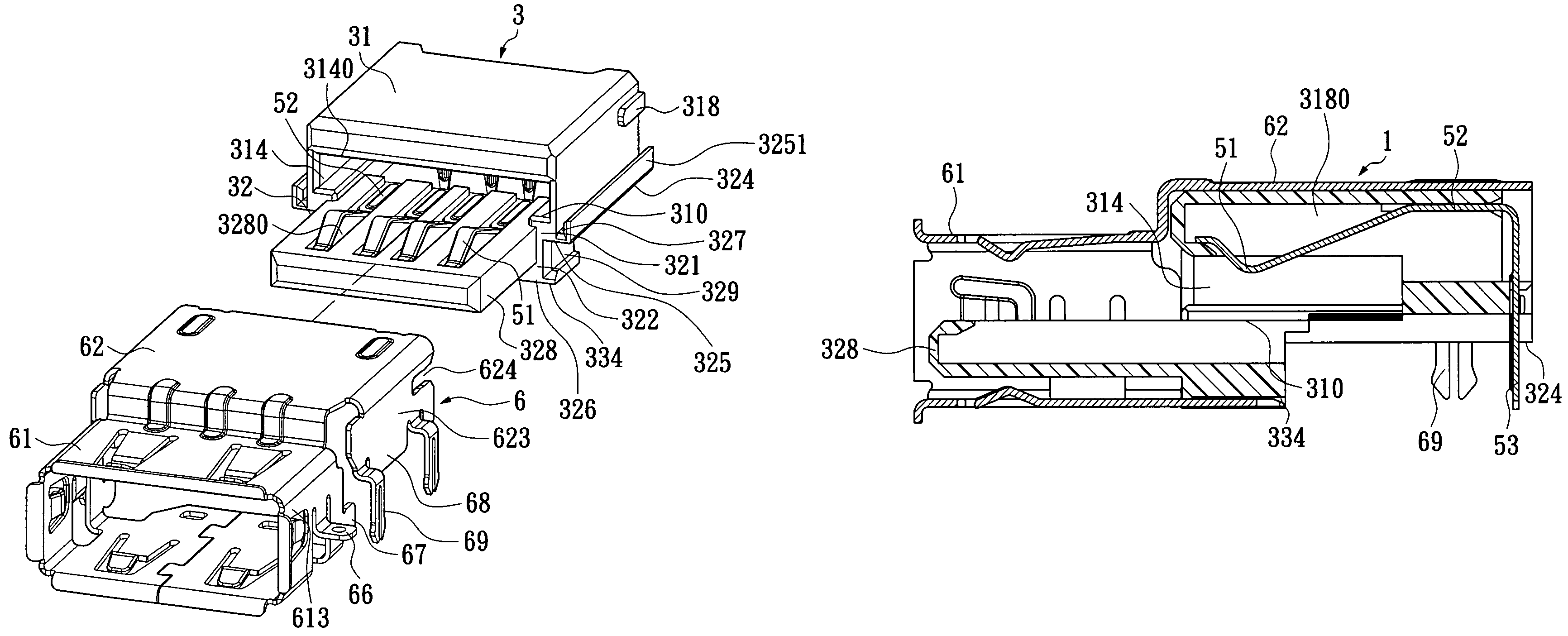
[0007]An object of the present invention is to provide a low-profile electrical connector which can not only engage with various butting assemblies, but also save internal space of computers.
[0010]Another object of the present invention is to provide a low-profile electrical connector device which ensures that the low-profile electrical connector can not only engage with various butting assemblies, but also save internal space of computers.
[0012]Since the slot has the plurality of first terminal receiving grooves formed at intervals in one sidewall thereof and the tongue plate has the second terminal receiving grooves formed in the top surface thereof, the first terminal receiving grooves and the second terminal receiving grooves lie in different planes, so that the low-profile electrical connector can engage with various butting assemblies. Furthermore, when the low-profile electrical connector is mounted on the circuit board, a part of the connector is located below the circuit board, so the height of the exposed portion of the low-profile electrical connector above the circuit board is reduced, thereby saving the circuit board space.

Problems solved by technology

However, the electrical connectors occupy much space themselves, which does not meet the development of computers.
However, the conventional low-profile electrical connectors are limited in their structures so that they cannot engage with various butting assemblies.

Method used


Image

  • Low-profile electrical connector and device thereof
  • Low-profile electrical connector and device thereof
  • Low-profile electrical connector and device thereof

Examples


Embodiment Construction

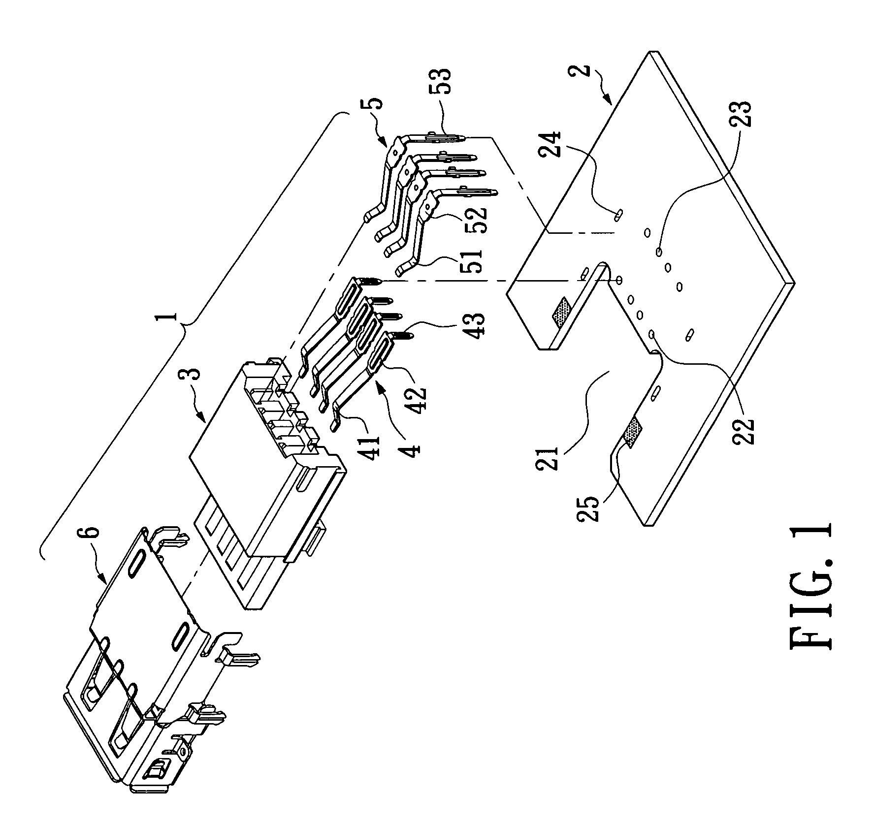
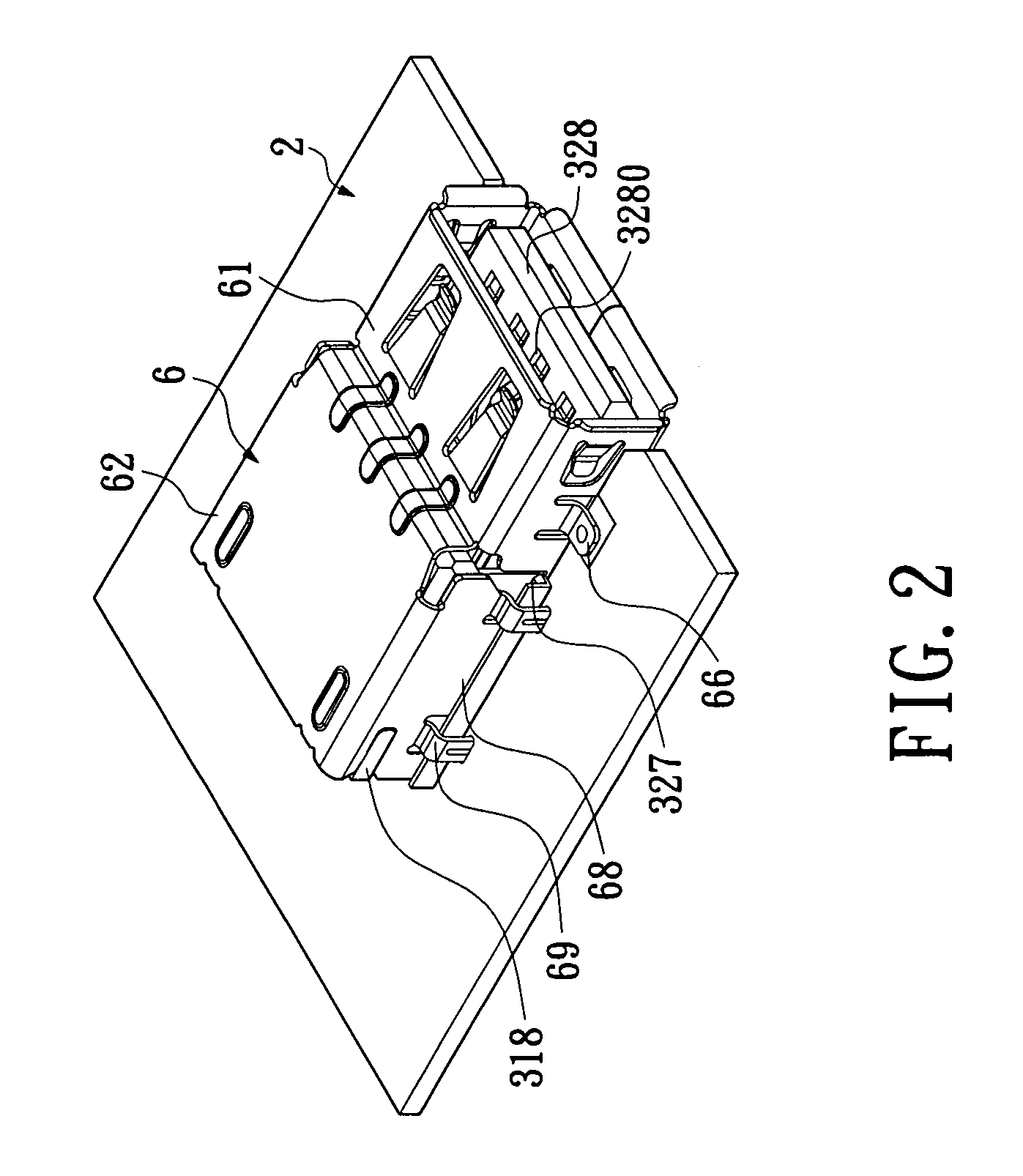
[0025]To further understand features and technical contents of the present invention, please refer to the drawings and the following detailed description related the low-profile electrical connector according to the present invention.

[0026]Please refer to FIG. 1 and FIG. 2, a low-profile electrical connector 1 of the present invention is mounted on a circuit board 2. The circuit board 2 has a cutout 21 formed in one end thereof, a plurality of second terminal welding holes 22 and a plurality of first terminal welding holes 23 formed in the circuit board 2 behind the cutout 21, and a plurality of pin holes 24 and two welding pads 25 respectively located on the two sides of the cutout 21, wherein the welding pads 25 are closer to the front end of the cutout 21 than the pin holes 24.

[0027]The low-profile electrical connector 1 includes an insulating body 3, a plurality of first conductive terminals 5 and a plurality of second conductive terminals 4 held in the insulating body 3, and a ...


PUM


Abstract

A low-profile electrical connector mounted on a circuit board includes an insulating body. The insulating body includes a main body portion, a middle portion and a tongue plate. The main body portion has a slot concavely formed in a front end thereof, and at least one sidewall of the slot has a plurality of first terminal receiving grooves formed at intervals therein. The middle portion is formed by a bottom surface of the main body portion partially extending downwards. The tongue plate extends forwards from the middle portion and has a plurality of second terminal receiving grooves formed at intervals therein. A plurality of conductive terminals are respectively correspondingly received in the terminal receiving grooves. Comparing with conventional low-profile electrical connectors, the present invention can not only engage with various butting assemblies, but also save internal space of computers.

Description

BACKGROUND OF THE INVENTION[0001]1. Field of the Invention[0002]The present invention relates to an electrical connector, and more especially to a low-profile electrical connector and device thereof.[0003]2. Description of Related Art[0004]With the development of science and technology and people's living standards, computers become an important part of people's lives. Especially, notebook computers are widely used in people's lives because of their portability. For meeting the increasing requirements of people for notebook computers, notebook computers must be smaller, lighter and thinner, which requires that electrical connectors which are important components of notebook computers occupy the smallest space without affecting normal electrical connection.[0005]Conventional electrical connectors are directly connected to circuit boards. However, the electrical connectors occupy much space themselves, which does not meet the development of computers. With the development of computer ...

Claims


Application Information

Patent Timeline
Patent Type & Authority Patents(United States)
IPC IPC(8): H01R33/00
CPCH01R13/50H01R12/724H01R13/6594
Inventor YAO, GUILIN
Owner LOTES
Learn More