
Vane platform cooling

a technology of platform cooling and cooling film, which is applied in the direction of liquid fuel engines, marine propulsion, vessel construction, etc., can solve the problems of shell and core(s) being damaged

Active Publication Date: 2009-12-01
RTX CORP
View PDF5 Cites 50 Cited by
  • Summary
  • Abstract
  • Description
  • Claims
  • Application Information

AI Technical Summary

Benefits of technology

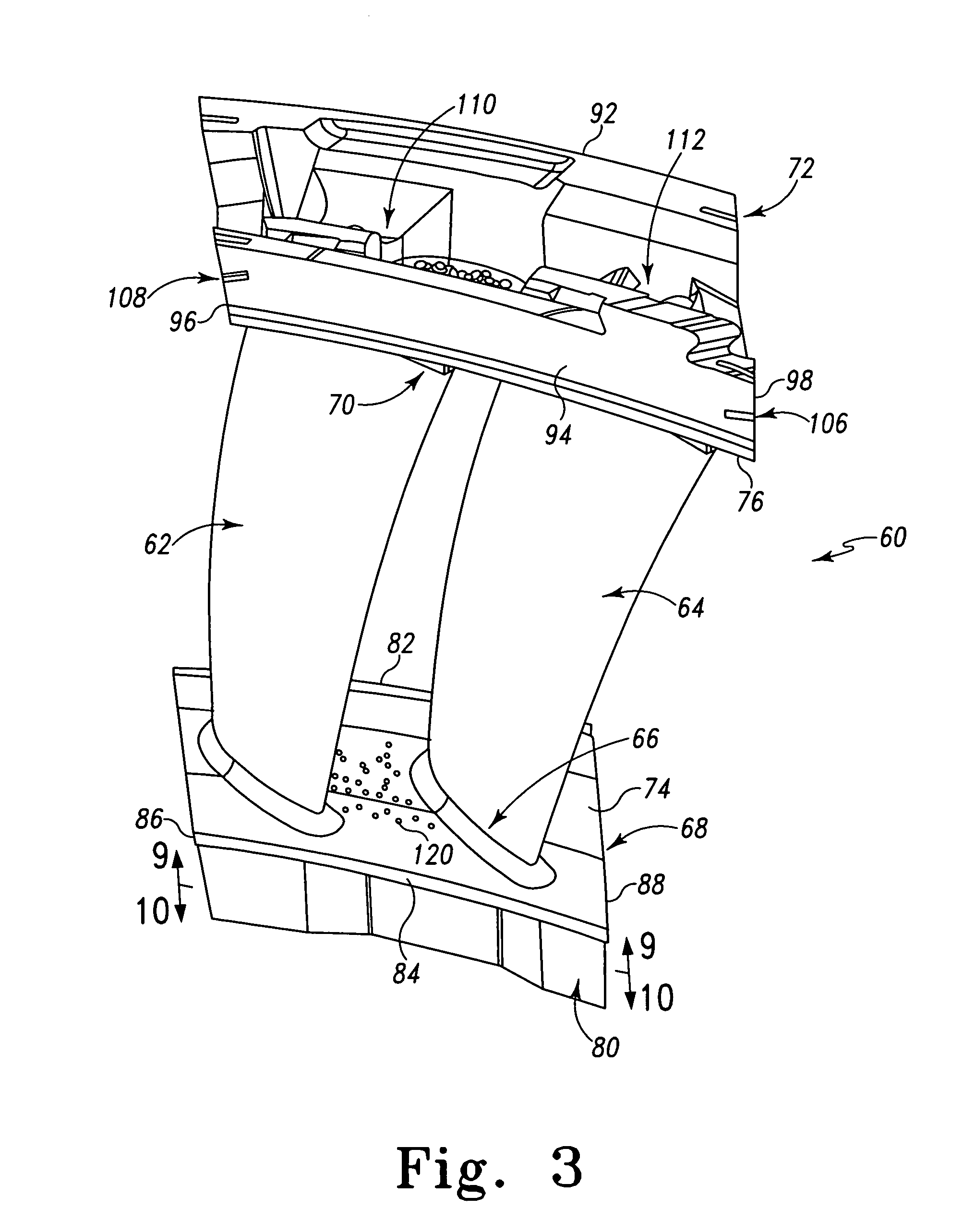
"The invention is a vane cluster that includes a platform, a shroud, and at least two airfoils. Each airfoil has a pressure side and a suction side. The cluster also has a cooling passageway system with at least one inlet and two feed passageways. The first airfoil has a platform cooling plenum on its pressure side and the second airfoil has a platform cooling plenum on its suction side. The cluster may also include a casting and covers enclosing the cooling plenums. The technical effect of this invention is to provide an improved cooling system for the vane cluster that facilitates better cooling performance."

Problems solved by technology

The shell and core(s) may be destructively removed (e.g., by mechanical means and chemical means, respectively).

Method used


Image

  • Vane platform cooling
  • Vane platform cooling
  • Vane platform cooling

Examples


Embodiment Construction

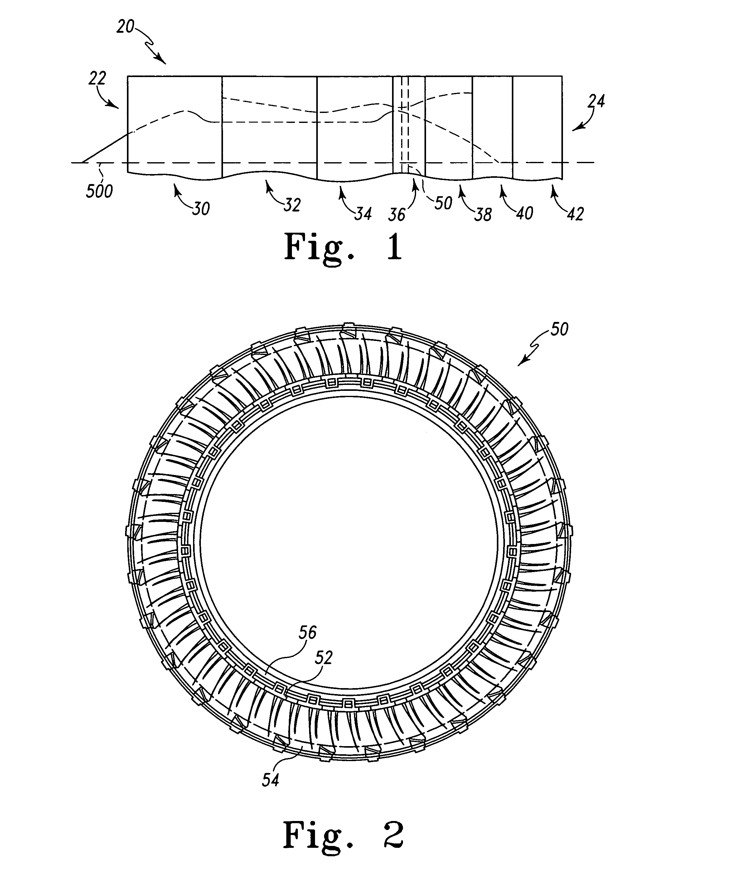
[0019]FIG. 1 shows a gas turbine engine 20 having a central longitudinal axis 500 and extending from an upstream inlet 22 to a downstream outlet 24. From upstream to downstream, the engine may have a number of sections along a core flowpath. From upstream to downstream, the sections may include a low speed / pressure compressor (LPC) 30, a high speed / pressure compressor (HPC) 32, a combustor 34, a high speed / pressure turbine (HPT) 36, a low speed / pressure turbine (LPT) 38, an augmentor 40, and an exhaust duct / nozzle 42. Each of the compressor and turbine sections may include a number of blade stages interspersed with a number of vane stages. The blades of the LPC and LPT are mounted on a low speed spool for rotation about the axis 500. The blades of the HPC and HPT are mounted on a high speed spool for such rotation.

[0020]As is discussed in further detail below, one or more of the vane stages may be formed as a cluster ring. For example, a second vane stage 50 of the HPT 36 is schemat...


PUM


Abstract

A vane cluster has a platform, a shroud, and at least first and second airfoils extending between an outer face of the platform and an inner face of the shroud. Each airfoil has a pressure side and a suction side. The pressure side of the first airfoil faces the suction side of the second airfoil. The cluster includes a cooling passageway system. The system includes at least one inlet in the shroud. At least one first feed passageway extends from the shroud to the platform through the first airfoil. At least one second feed passageway extends from the shroud to the platform through the second airfoil. A first platform cooling plenum is to the pressure side of the first airfoil. A second platform cooling plenum is to the suction side of the first airfoil.

Description

U.S. GOVERNMENT RIGHTS[0001]The invention was made with U.S. Government support under contract F33657-99-D-2051-0014 awarded by the U.S. Air Force. The U.S. Government has certain rights in the invention.BACKGROUND OF THE INVENTION[0002]The invention relates to cooling of high temperature components. More particularly, the invention relates to film cooling of gas turbine engine components.[0003]In the aerospace industry, a well-developed art exists regarding the cooling of components such as gas turbine engine components. Exemplary components are gas turbine engine blades and vanes. Exemplary blades and vanes airfoils are cooled by airflow directed through the airfoil to be discharged from cooling holes in the airfoil surface. Also, there may be cooling holes along the vane shroud or vane or blade platform. The cooling mechanisms may include both direct cooling as the airflow passes through the component and film cooling after the airflow has been discharged from the component but p...

Claims


Application Information

Patent Timeline
Patent Type & Authority Patents(United States)
IPC IPC(8): F01D5/18
CPCF01D5/186F01D25/12F05D2240/81Y02T50/676Y02T50/60
Inventor WALZ, CHRISTOPHER S.WASSERMAN, DAVID J.WONG, ALEX D.HLAVATY, KIRK D.EVANS, DONALD E.
Owner RTX CORP
Learn More