
Lunar phase display mechanism

Inactive Publication Date: 2009-10-27
RICHEMONT INT
View PDF20 Cites 9 Cited by
  • Summary
  • Abstract
  • Description
  • Claims
  • Application Information

AI Technical Summary

Benefits of technology

[0005]Therefore, it is an object of the present invention, in contrast to known devices of this kind, to realise a lunar phase display that allows, by choice, to account in the display for the different appearance of the lunar phases as seen from the earth either on the northern or the southern hemisphere and more particularly at the latitudes between the poles as well, and that allows by simple means to render as realistic as possible the position as well as the size of the bright and dark parts of the lunar surface as they are seen from earth.
[0008]In this way it is possible with a single watch and simple adjustment of this disc, that is, without any structural changes, to display either the lunar phases as they are seen in the northern or southern hemisphere, or with fine adjustment of this disc; to account for the inclined position of the crescent that is seen by observers.

Problems solved by technology

However, said mechanism yields neither a selective display of the lunar phases in a shape close to reality just in one hemisphere nor a realistic display that would account for further aspects such as the inclined crescents seen at latitudes between the poles.

Method used


Image

  • Lunar phase display mechanism
  • Lunar phase display mechanism
  • Lunar phase display mechanism

Examples


Embodiment Construction

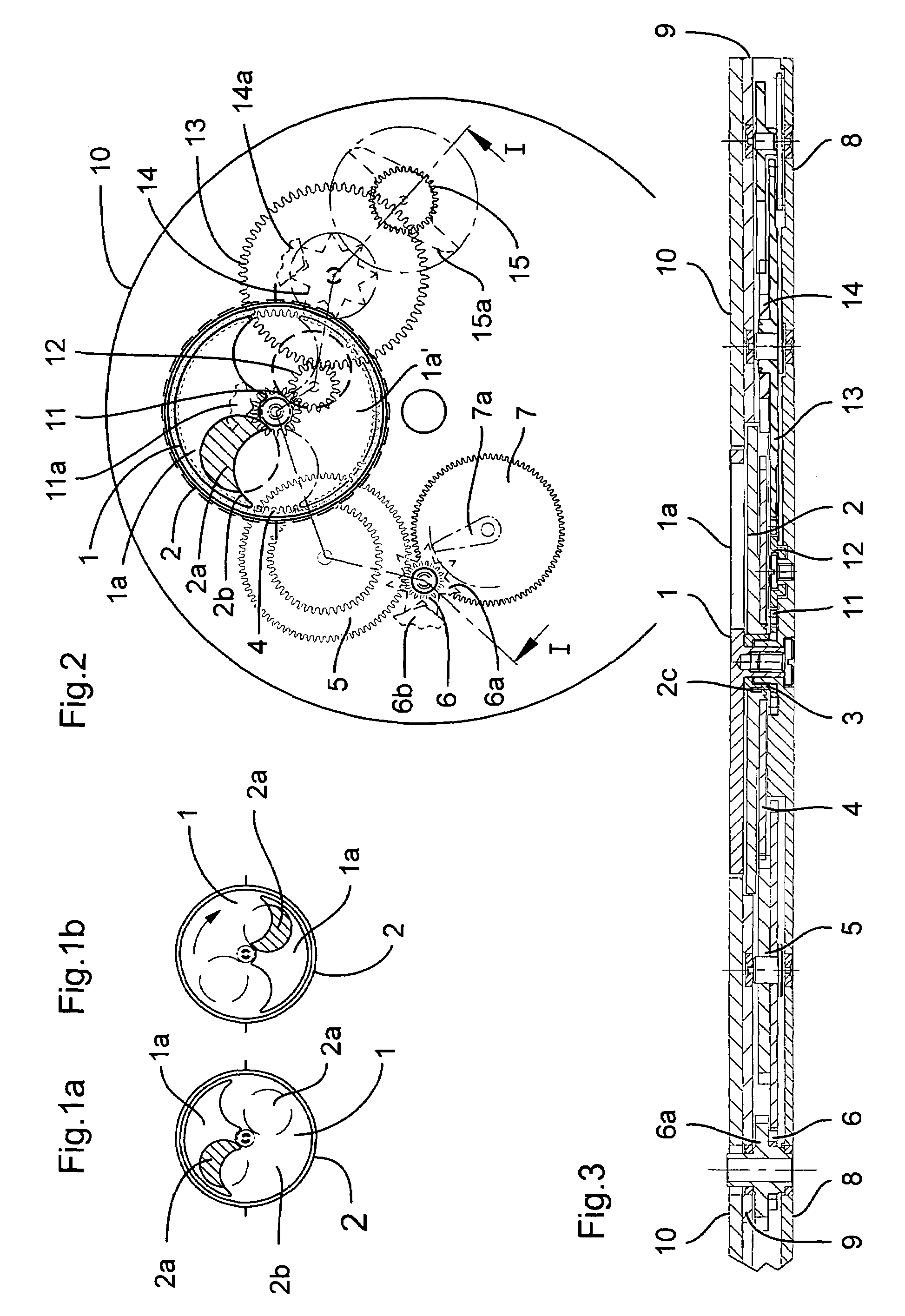
[0022]The invention will now be described in detail while referring to the appended drawings.

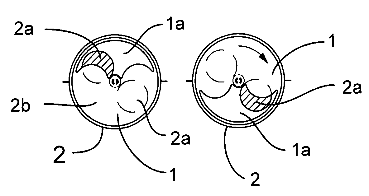
[0023]The principle of a mechanism according to the present invention will first be outlined with the help of FIGS. 1a and 1b.

[0024]A lunar phase display mechanism in accordance with the present invention has a first, upper disc which is called lunar display disc 1. In the first embodiment, this disc 1 is fitted with one window 1a as schematically shown in FIG. 1a. Here this window is formed as an outwardly arched shape having two further arched segments inside, such as is generally customary in lunar phase displays.

[0025]Such a mechanism further includes another, lower disc which is called the lunar disc 2. This lunar disc 2 is placed concentrically beneath the lunar display disc 1, as shown schematically in FIG. 1a, and functions as it were as a background scene seen through window 1a of the lunar display disc 1. To this end, a graphic design which, in combination with window 1a of the lu...


PUM


Abstract

A lunar phase display mechanism includes an upper disc which is the lunar display disc and a lower disc mounted concentrically to this disc. One of the discs is mounted so that during normal operation of the mechanism that one disc rotates relative to the other disc, and the other disc is mounted in a stationary position during normal operation of the mechanism while this position can be changed by a rotary motion. The gear train driving the rotating disc allows that the direction of rotation of this disc can be reversed so that the different appearance of the lunar phases at the latitudes of the earth and, in particular, in the northern and southern hemisphere can be taken into account in the display.

Description

BACKGROUND OF THE INVENTION[0001]The present invention relates to a lunar phase display mechanism having an upper disc, the lunar display disc, and a lower disc, the lunar disc, mounted concentrically to the upper disc, one of these discs being mounted in such a way that it rotates relative to the other disc during normal operation of the mechanism.DESCRIPTION OF THE RELATED ART[0002]Such mechanisms basically are known, particularly so in complex watches, and are used for instance as a secondary display in wristwatches. However, the lunar phases seen by an observer have an appearance that differs depending on his position on the globe, in particular on the latitude, in a way already explained in the European patent application EP 1 445 672 originating from the International Watch Corporation (IWC). The part of the lunar surface that is illuminated by the sun and can be seen by an observer on earth depends in fact on the relative positions of the sun, earth and moon, and the effectiv...

Claims


Application Information

Patent Timeline
IPC IPC(8): G04B19/26G09B23/00
CPCG04B19/268
Inventor ZIMMERMANN, DENISLARSONNEUR, RENEBUHLER, PHILIPP
Owner RICHEMONT INT
Learn More