
Socket adaptor apparatus

a socket and socket technology, applied in the direction of fixed connections, coupling device connections, instruments, etc., can solve the problems of difficult disassembly and removal of sockets, high cost of sockets, complex contact shapes of sockets, etc., and achieve the effect of easy cleaning of sockets, convenient mounting or disassembly of sockets, and convenient re-use of sockets

Active Publication Date: 2009-10-13
LTI HLDG INC
View PDF5 Cites 3 Cited by
  • Summary
  • Abstract
  • Description
  • Claims
  • Application Information

AI Technical Summary

Benefits of technology

"The invention is a socket adaptor that solves the problem of difficulty in mounting and dismounting sockets on circuit substrates. It is made of an insulating material with through holes containing probe pins that can be easily mounted or dismounted. The probe pins have clips that engage contacts when inserted, and a spring member is accommodated in each through hole to bias the probe pins. The main adaptor body has slots for sliding the probe pins, and the cross-sectional shape of the through holes is rectangular or round. The clipping part includes elastically deformable arms and a protruding pin, and the spring member is received between the arms and the protruding pin. The invention allows for easy mounting and dismounting of sockets on circuit substrates, and easy cleaning or reuse of the removed sockets."

Problems solved by technology

For this mounting, the contacts of a socket and the circuit substrate are directly soldered as described above, with a result that it becomes difficult to disengage the socket.
Although it is conceivable to substitute the contacts of the socket with probe pins, the shape of the contact of a socket is complicated and, if it is used, the cost of the socket becomes extremely high.

Method used


Image

  • Socket adaptor apparatus
  • Socket adaptor apparatus
  • Socket adaptor apparatus

Examples


Embodiment Construction

[0028]The above and other objects and features of the present invention will become apparent from the detailed description of the invention along with the drawings and appended claims.

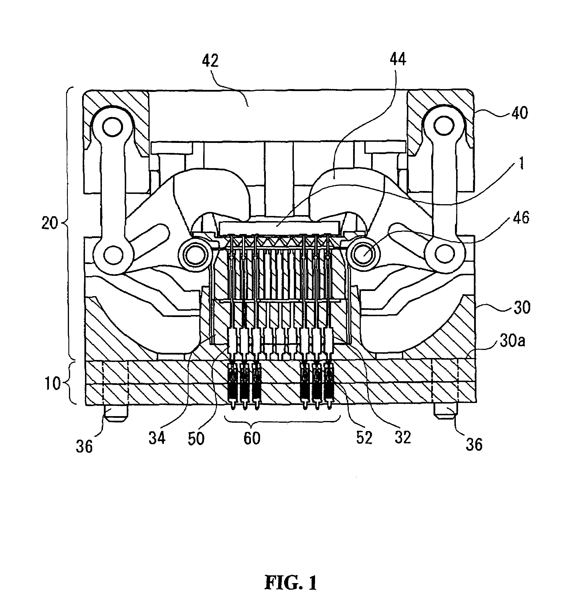
[0029]FIG. 1 shows an example of a socket that has connected thereto a socket adaptor made according to a first preferred embodiment of this invention. Socket adaptor 10 is to be connected between a circuit substrate and the socket 20, thereby offering an electrical interface between the socket and the circuit substrate. It is possible to mount various packages such as BGA, LGA, PLCC and the like on socket 20. Socket 20, as shown in FIG. 1, includes a cover member 40 which is capable of a reciprocating motion toward and away from base member 30 and a plurality of elongated contact members 50 which have been mounted in base member 30.

[0030]A pair of coil springs (not shown in the drawings) is interposed between cover member 40 and base member 30 biasing cover member 40 is away from the base member. A ge...


PUM


Abstract

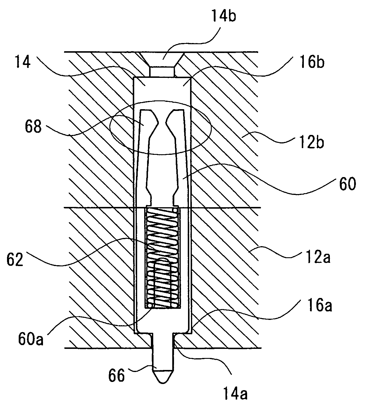
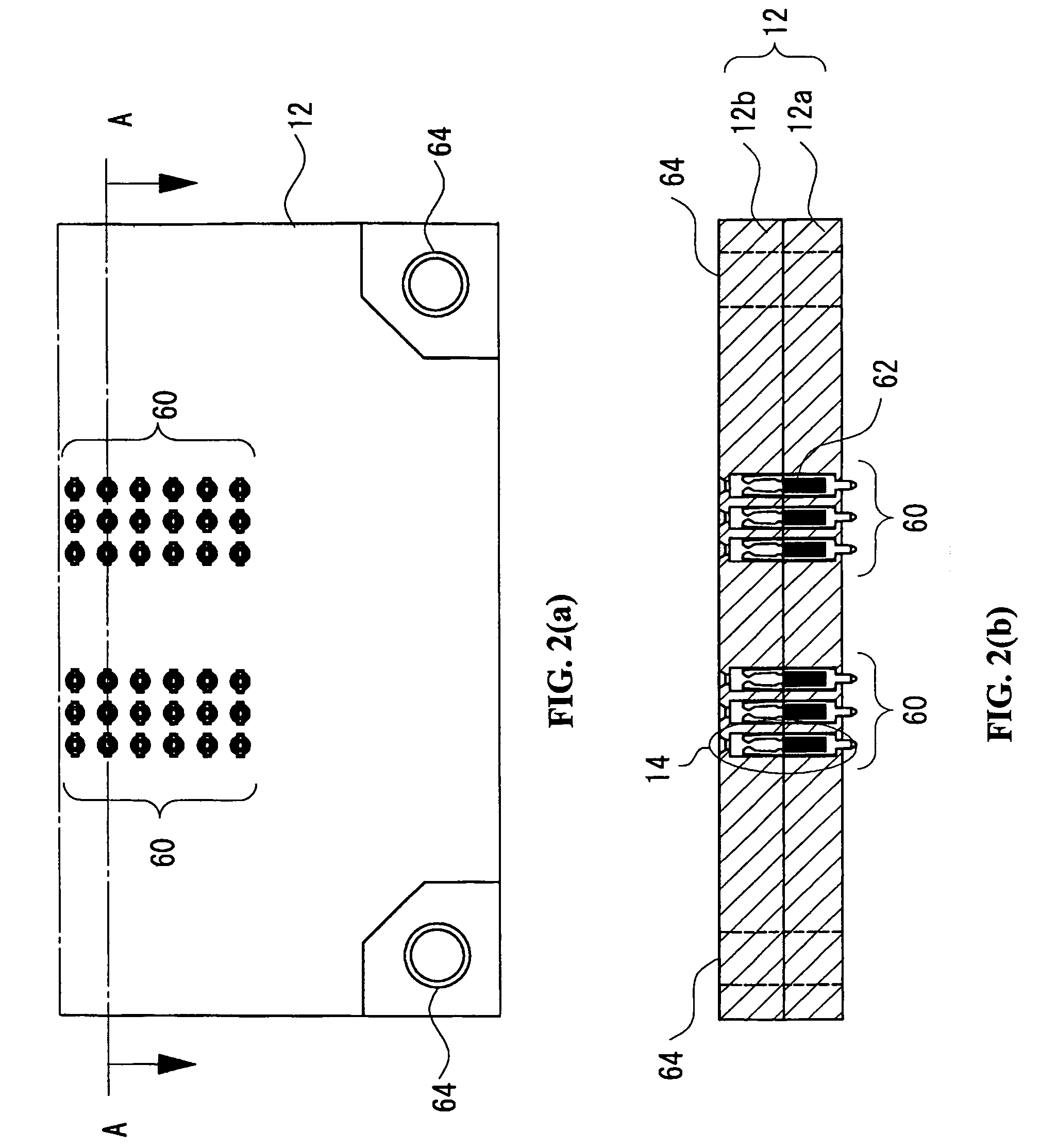
A socket adaptor 10 made of an electrically insulating material has a main adaptor body 12 on which a plurality of through holes 14 containing an upper opening and a lower opening has been formed. In certain preferred embodiments a probe pin 60 and coil spring 62 is placed in each through hole 14. An electrical engagement clipping part 68 for clipping a contact inserted in a respective through hole from said upper opening is formed on the upper end of each probe pin 60. The coil spring 62 is installed on each probe pin and biases the respective probe pin toward a position so that a tip formed on the lower end of the probe pin protrudes from the lower opening.

Description

FIELD OF THE INVENTION[0001]This invention relates generally to an adaptor for sockets that mount a semiconductor device and more particularly to a socket adaptor that provides an interface of an electrical connection between contacts of a socket and electrodes of a circuit substrate.BACKGROUND OF THE INVENTION[0002]A conventional socket for a BGA package is disclosed in Japanese Patent No. 3737078, issued Nov. 4, 2005, by way of example. This patent shows a socket that is capable of mounting or dismounting an electronic device that includes a semiconductor device of the surface mount type such as BGA or CSP.[0003]According to the patent, the socket includes a base member, a cover member, a plurality of contacts, an adaptor which is capable of moving in a direction toward or away from the base member and which offers a mounting surface for a BGA, a latch member rotatably mounted on the base member and a positioning mechanism that moves in linkage with the movement of the cover membe...

Claims


Application Information

Patent Timeline
Patent Type & Authority Patents(United States)
IPC IPC(8): H01R12/00H01R12/71H01R12/55
CPCG01R1/0483H01R12/57H05K7/1084H01R13/112H01R13/2421H01R13/111H01R33/76
Inventor TAKAHASHI, HIDEYUKIIKEYA, KIYOKAZU
Owner LTI HLDG INC
Learn More