
Microsurgical probe

a micro-scopy and probe technology, applied in the field of micro-scopy probes, can solve the problems of limited ability of the surgeon to dispose of a conventional vitrectomy probe, and achieve the effect of high speed

Active Publication Date: 2009-10-13
ALCON INC
View PDF50 Cites 17 Cited by
  • Summary
  • Abstract
  • Description
  • Claims
  • Application Information

AI Technical Summary

Problems solved by technology

However, a surgeon is limited in how close to the retina he or she can dispose a conventional vitrectomy probe due to the geometry of the probe tip and the cutting port.

Method used


Image

  • Microsurgical probe
  • Microsurgical probe
  • Microsurgical probe

Examples


Embodiment Construction

[0017]The preferred embodiments of the present invention and their advantages are best understood by referring to FIGS. 1 through 6 of the drawings, like numerals being used for like and corresponding parts of the various drawings.

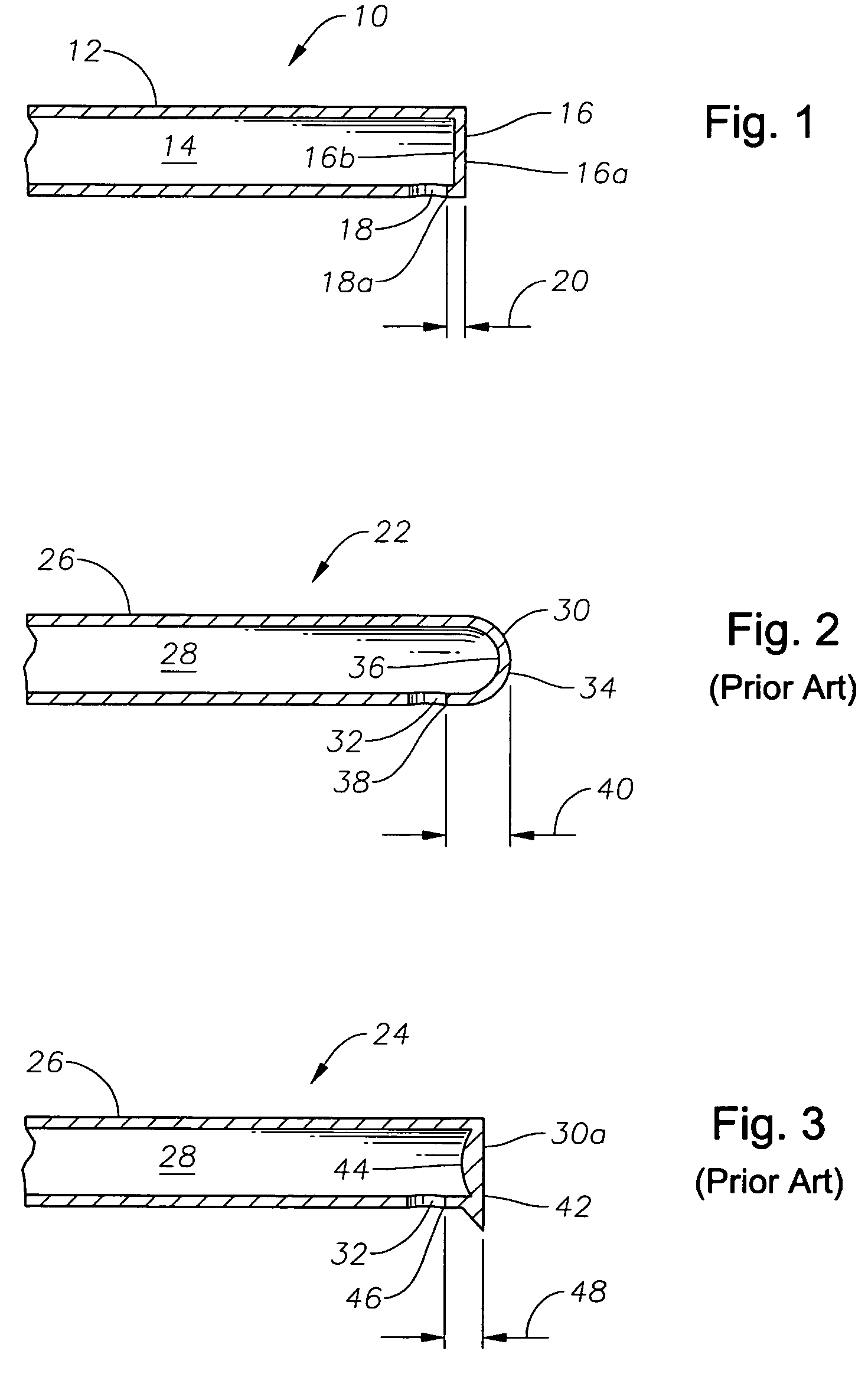
[0018]FIG. 1 shows the distal portion of a vitrectomy probe 10 according to a preferred embodiment of the present invention. Probe 10 generally includes a tubular body 12 having an inner bore 14, a closed distal tip 16, and a port 18 providing access to inner bore 14. Tubular body 12 is preferably made of stainless steel. An inner cutting member (not shown) longitudinally reciprocates within inner bore 14 so as to cut tissue aspirated into inner bore 14 via port 18 by a surgical console (not shown). Distal tip 16 has a flat outer surface 16a and a flat inner surface 16b. Probe 10 preferably has a 20 gage to 25 gage diameter.

[0019]FIGS. 2 and 3 show the distal portions of conventional vitrectomy probes 22 and 24, respectively. Probes 22 and 24 each generall...


PUM

PropertyMeasurementUnit
thicknessaaaaaaaaaa
speedaaaaaaaaaa
transparentaaaaaaaaaa

Abstract

Microsurgical probes having a distal tip with a flat outer surface and a flat inner surface, and methods of forming such probes, are disclosed.

Description

[0001]This application claims the priority of U.S. Provisional Application No. 60 / 725,526 filed Oct. 11, 2005.FIELD OF THE INVENTION[0002]The present invention generally pertains to microsurgical probes and more particularly to ophthalmic microsurgical probes such as vitrectomy probes.DESCRIPTION OF THE RELATED ART[0003]Posterior segment ophthalmic surgical procedures generally require the cutting and / or removal of the vitreous humor, a transparent jelly-like material that fills the posterior segment of the eye. The vitreous humor, or vitreous, is composed of numerous microscopic fibers that are often attached to the retina. Therefore, cutting and removal of the vitreous must be done with great care to avoid traction on the retina, the separation of the retina from the choroid, a retinal tear, or, in the worst case, cutting and removal of the retina itself.[0004]The use of microsurgical cutting probes in posterior segment ophthalmic surgery is well known. Such vitrectomy probes are ...

Claims


Application Information

Patent Timeline
Patent Type & Authority Patents(United States)
IPC IPC(8): B21D17/04
CPCA61F9/00736B21D22/14B21D41/045B21G1/08B21J5/063B23K11/0046B23K11/02B23K11/16B23K33/006B21K21/14B23K2201/06A61F9/00763B23K2101/06A61B18/18A61B17/32
Inventor MAURER, JR., ROBERT S.BURKMAN, BRIAN D.MARTIN, RANDALL R.KETNER, JR., DALE E.
Owner ALCON INC
Learn More