
Automatic built-in air nozzle

a built-in air nozzle and automatic technology, which is applied in the direction of fluid mattresses, sofas, packaged goods, etc., can solve the problems of still required caps and troublesome user removal of caps before inflating inflatable products, and achieve the effect of less space and less cos

Active Publication Date: 2009-10-06
WANG CHENG CHUNG
View PDF10 Cites 9 Cited by
  • Summary
  • Abstract
  • Description
  • Claims
  • Application Information

AI Technical Summary

Benefits of technology

The automatic air nozzle significantly reduces user effort and ensures a tighter seal by automating the opening and closing of the air path, minimizing air leakage and improving the overall inflation and deflation process.

Problems solved by technology

Even when the air nozzle is unidirectional to have a self-sealing function, the cap is still required.
That unidirectional function of the conventional air nozzle can not fully ensure that air will not escape from the inflatable product, so the cap is still necessary.
Therefore, it is very troublesome for the user to remove the cap before inflating the inflatable product and to return the cap after the inflatable product has been inflated.

Method used


Image

  • Automatic built-in air nozzle
  • Automatic built-in air nozzle
  • Automatic built-in air nozzle

Examples


third embodiment

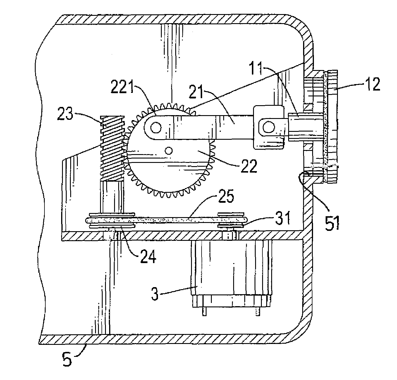
[0034]With reference to FIG. 3A, the automatic air nozzle of the present invention is shown and includes a motor (3) having thereon a first wheel (31), a worm shaft (23) having a second wheel (24) formed with the worm shaft (23) and connected to the first wheel (31) via a belt (25), a worm gear (22) meshed with the worm shaft (23), a linkage (21) eccentrically and pivotally connected to the worm gear (22) at location (221) and a valve (12) formed on a free end of a connection seat (11) which is firmly connected to a top face (1) of the valve (12) and pivotally formed on a free end of the linkage (21). The linkage (21) is pivotally connected to the worm gear (22) via a shaft (221) on a side face of the worm gear (22). A central shaft (222) is formed at a center of the worm gear (22) to be firmly connected to the inflatable object (5), as shown in FIGS. 3B-3F.

[0035]After the automatic air nozzle of the present invention is firmly mounted inside the inflatable object (5) via the centra...

fourth embodiment

[0036]With reference to FIG. 4, the present invention is shown, and this embodiment is substantially the same as that as shown in FIG. 3A. The only difference therebetween is that the worm shall (23) is directly connected to the motor (3). Therefore, the activation of the motor (3) is able to drive the worm shall (23) to rotate. Accordingly, the valve (12) is able to close / open the air path (51) of the inflatable object (5).

[0037]With reference to FIGS. 5A and 5B, an inflatable mattress (5′) is shown and has a controller (4) and a casing (41) embedded inside the inflatable mattress (5′). The automatic air nozzle of the present invention is installed inside the casing (41). The inflatable mattress (5′) further has a backrest parcel (51′) located at an upper portion of the inflatable mattress (5′) and a leg-rest parcel (52) located at a lower portion of the inflatable mattress (5′). In order to inflate the backrest parcel (51′) and the leg-rest parcel (52), the inflatable mattress (5′...


PUM

PropertyMeasurementUnit
rotationaaaaaaaaaa
movementaaaaaaaaaa
shapeaaaaaaaaaa

Abstract

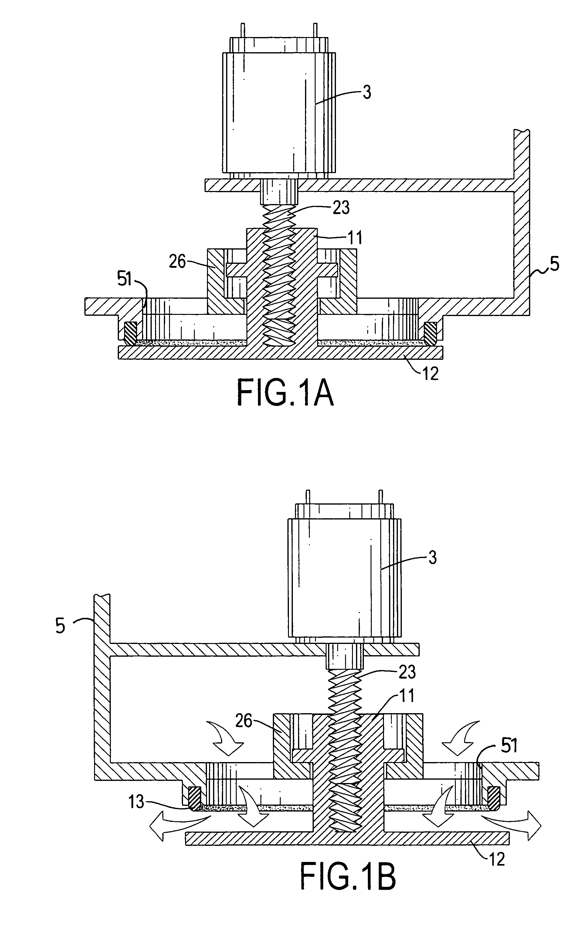
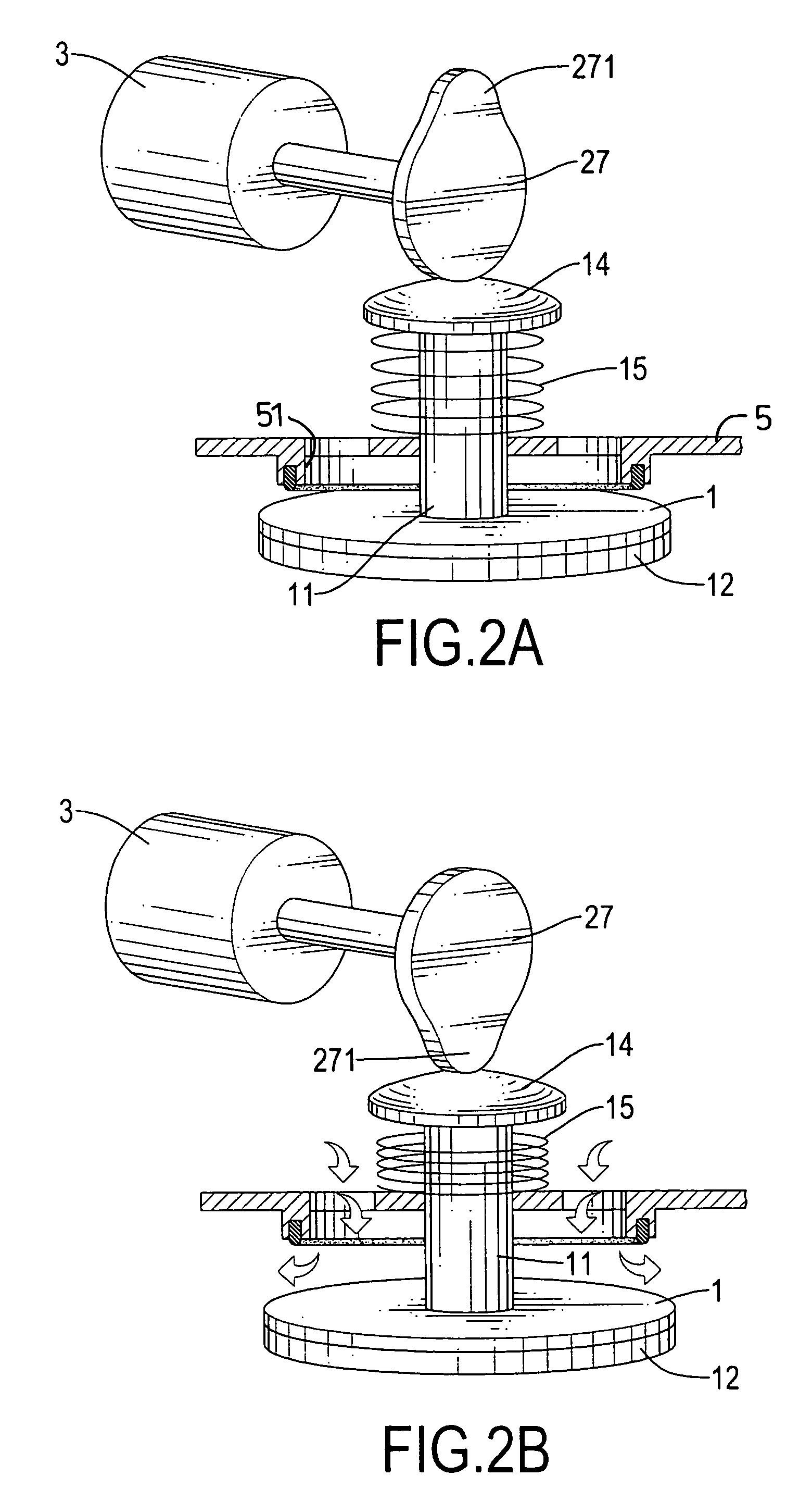
An automatic air nozzle includes a valve adapted to engage with a peripheral side face defining the air path inside the inflatable object. A linking element has a first end operably connected to the valve and a second end. A motor is operably connected to the second end of the linking element so as to drive the valve to move linearly relative to the inflatable object to open / close the air path automatically.

Description

BACKGROUND OF THE INVENTION[0001]1. Field of the Invention[0002]The present invention relates to an automatic built-in air nozzle and, more particularly, to an automatic built-in air nozzle to automatically close an air path in an inflatable object after inflation of the inflatable object is finished.[0003]2. Description of the Prior Art[0004]A conventional air nozzle is provided to inflatable products, such as an inflatable swimming pool, animal-figured toys or the like. After an air pump has been used to pump air into the inflatable product, in order to prevent air leakage from the air nozzle, a cap is provided manually to block the air path of the conventional air nozzle. Even when the air nozzle is unidirectional to have a self-sealing function, the cap is still required. That unidirectional function of the conventional air nozzle can not fully ensure that air will not escape from the inflatable product, so the cap is still necessary. Therefore, it is very troublesome for the us...

Claims


Application Information

Patent Timeline
Patent Type & Authority Patents(United States)
IPC IPC(8): B65B3/16
CPCF16K31/04F16K31/54F16K31/52408F04D25/084
Inventor WANG, CHENG-CHUNG
Owner WANG CHENG CHUNG
Learn More