
Method and apparatus for fixing a graft in a bone tunnel

a bone tunnel and graft technology, applied in the field of surgical methods and equipment, can solve problems such as partial or permanent disability

Active Publication Date: 2009-09-29
DEPUY SYNTHES PROD INC
View PDF121 Cites 63 Cited by
  • Summary
  • Abstract
  • Description
  • Claims
  • Application Information

AI Technical Summary

Benefits of technology

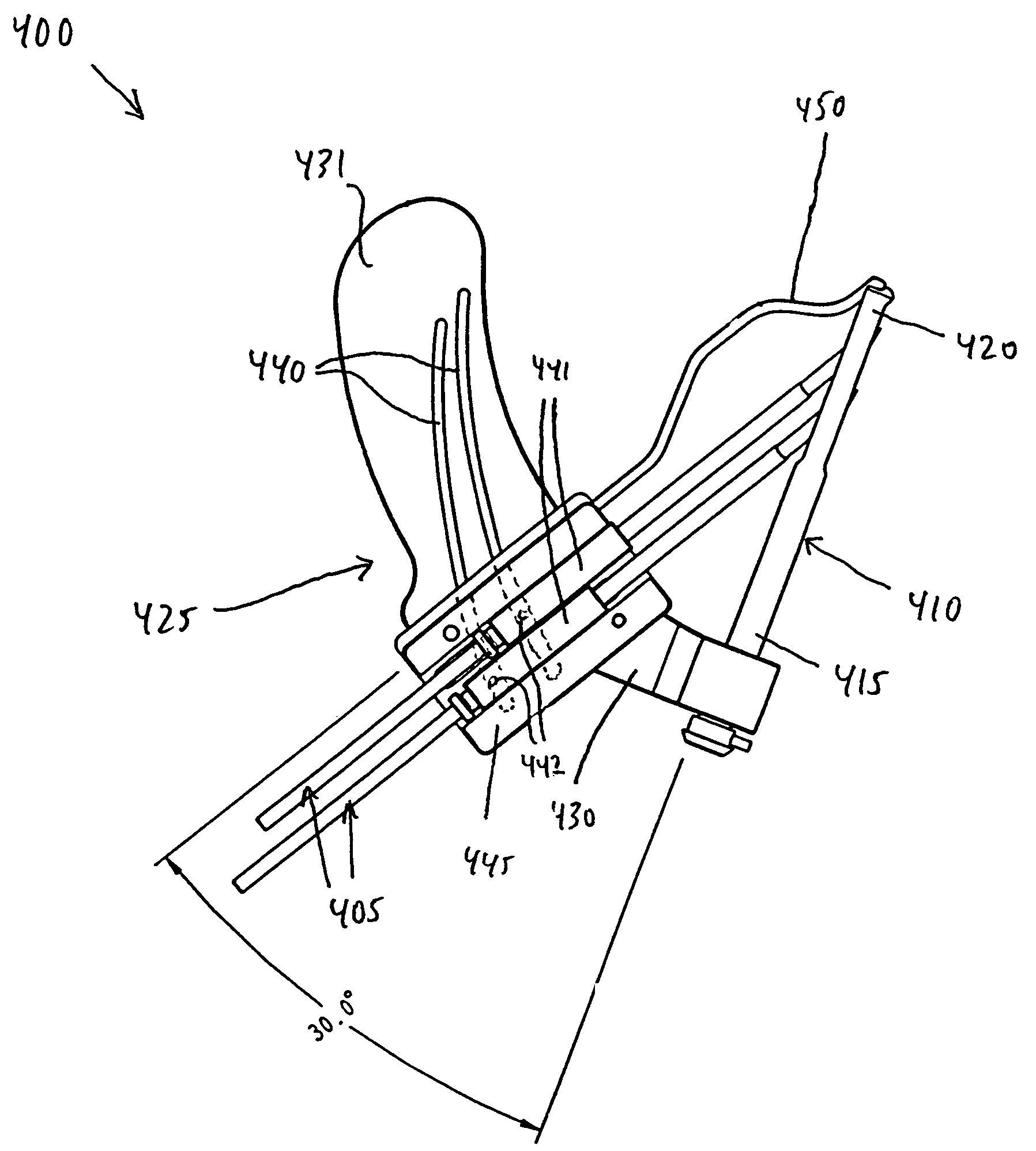
[0024]In accordance with a further feature of the present invention, there is provided an apparatus for positioning at least one cross-pin in a bone through a bone tunnel, the apparatus comprising: a bone tunnel guide rod having a proximal end and a distal end; a frame member having a base portion and an arm portion, the base portion attachable adjacent to the proximal end of the bone tunnel guide rod; at least one slot in the arm portion, the at least one slot being cammed outwardly toward the base portion relative to the bone tunnel guide rod; a drill guide member slidably connected with the at least one slot in the arm portion; and a probe connected to the drill guide member, the probe attachable to the distal end of the bone tunnel guide member such that the probe acts to guide member such that the probe acts to guide the positioning of the at least one cross-pin in the bone tunnel; and drilling means for drilling at least one cross-pin hole in the bone and across the bone tunnel, with the drilling means being supported in position by the drill guide member, the drill guide member in slidable connection with the frame member being in attachment with the bone tunnel guide rod, and the bone tunnel guide rod being inserted into the bone tunnel, and the probe being attached to the distal end of the bone tunnel guide rod to position the drill guide member to place at least one cross-pin hole in bone through a bone tunnel and allow the drill guide member to adjust relative to a changing angle and distance relative to a desired cross-pin site.

Problems solved by technology

If, however, the ligament or tendon is completely detached from its associated bone or bones, or if it is severed as the result of a traumatic injury, partial or permanent disability may result.
However, the femoral cross-pinning methods and apparatus that are presently known in the art do not address the use of a cross-pin in a tibial bone tunnel, which involves a different set of considerations.

Method used


Image

  • Method and apparatus for fixing a graft in a bone tunnel
  • Method and apparatus for fixing a graft in a bone tunnel
  • Method and apparatus for fixing a graft in a bone tunnel

Examples


Embodiment Construction

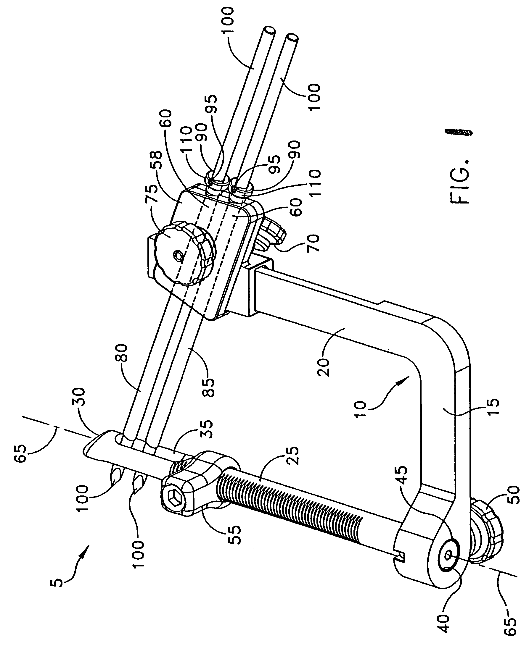
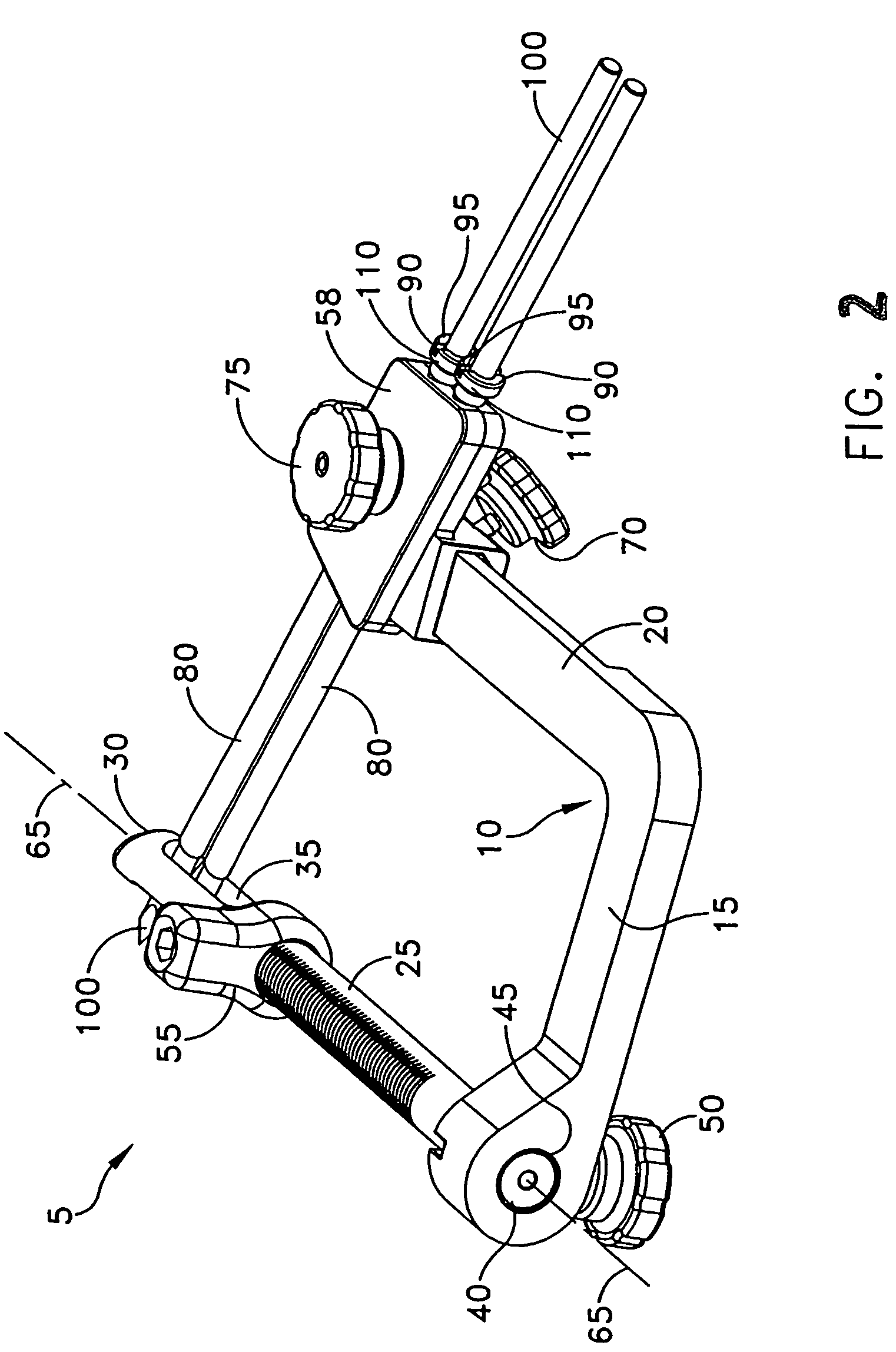
[0035]Looking first at FIGS. 1-10, there is shown a cross-pin guide assembly 5 for placement of at least one cross-pin (not shown in FIGS. 1-10) in a bone tunnel, such as the tibial tunnel of a knee joint. Cross-pin guide assembly 5 comprises an L-shaped member 10 having a base portion 15 and an arm portion 20. The arm portion 20 extends transversely to, and preferably is normal to, base portion 15.

[0036]Cross-pin guide assembly 5 further comprises a bone tunnel guide rod 25 which, adjacent to a first end 30 thereof, forms a diametrical, longitudinally-elongated passageway 35, and which, at a second end 40 thereof, is releasably connectable to base portion 15 of L-shaped member 10. In a preferred embodiment, bone tunnel guide rod 25 is cannulated along its axis 65 (see FIGS. 1-10) for placement on a guidewire (not shown in FIGS. 1-10). Bone tunnel guide rod 25 may be retained in a bore 45 formed in base portion 15 by a set screw 50. In an alternative embodiment, bone tunnel guide ro...


PUM


Abstract

A method and apparatus for fixing a ligament in a bone tunnel by cross-pinning the ligament in the bone tunnel.

Description

REFERENCE TO PENDING PRIOR PATENT APPLICATION[0001]This patent application is a continuation-in-part of prior U.S. patent application Ser. No. 10 / 364,786, filed Feb. 11, 2003 now U.S. Pat. No. 6,958,067 by Gregory Whittaker et al. for METHOD AND APPARATUS FOR FIXING A GRAFT IN A BONE TUNNEL, which patent application is hereby incorporated herein by reference.FIELD OF THE INVENTION[0002]This invention relates to surgical methods and apparatus in general, and more particularly to methods and apparatus for fixing a graft in a bone tunnel.BACKGROUND OF THE INVENTION[0003]The complete or partial detachment of ligaments, tendons and / or other soft tissues from their associated bones within the body are relatively commonplace injuries. Tissue detachment may occur as the result of an accident such as a fall, overexertion during a work-related activity, during the course of an athletic event, or in any one of many other situations and / or activities. Such injuries are generally the result of e...

Claims


Application Information

Patent Timeline
Patent Type & Authority Patents(United States)
IPC IPC(8): A61B17/60A61B17/56A61B17/16A61B17/17A61B19/00
CPCA61B17/1714A61B17/1637A61B17/1675A61B17/1764A61B2019/304A61B2019/462A61B2090/034A61B2090/062
Inventor WHITTAKER, GREGORY R.HYMAN, ERICORR, KEITHCALLAHAN, THOMAS
Owner DEPUY SYNTHES PROD INC
Learn More