
Automatically configuring vacuum contactor

a technology of automatic configuration and contactor, which is applied in the direction of magnets, magnets, instruments, etc., can solve the problems of time-consuming, complex configuration of contactor controllers for different vacuum contactor altitudes, and upset forces balance, and achieve the effect of superior coil actuation

Active Publication Date: 2009-09-22
ROCKWELL AUTOMATION TECH
View PDF4 Cites 4 Cited by
  • Summary
  • Abstract
  • Description
  • Claims
  • Application Information

AI Technical Summary

Benefits of technology

The present invention provides a contactor controller that can automatically configure itself for different types of vacuum contactors and operating altitudes. The controller uses a short pulse to determine the impedance of the coil without activating it, and a barometric pressure sensor to adjust the actuation power for altitude. The controller also monitors electrical flow to detect coil faults and can detect premature failure of the vacuum bottle caused by over stressing of the vacuum bottle. The test circuit uses a predetermined voltage and time to differentiate coil types without activating them. The controller also includes a fault detection function to alert the user when a fault is detected. The invention provides a simple method of distinguishing coil types without machine-readable labeling of the coils, and makes use of existing hardware for the purpose of characterizing the coil configuration.

Problems solved by technology

This balance of forces is upset if the vacuum contactor is moved to a different altitude having a different atmospheric pressure.
Configuration of the contactor controller for different vacuum contactors and altitudes is complex and time consuming.

Method used


Image

  • Automatically configuring vacuum contactor
  • Automatically configuring vacuum contactor
  • Automatically configuring vacuum contactor

Examples


Embodiment Construction

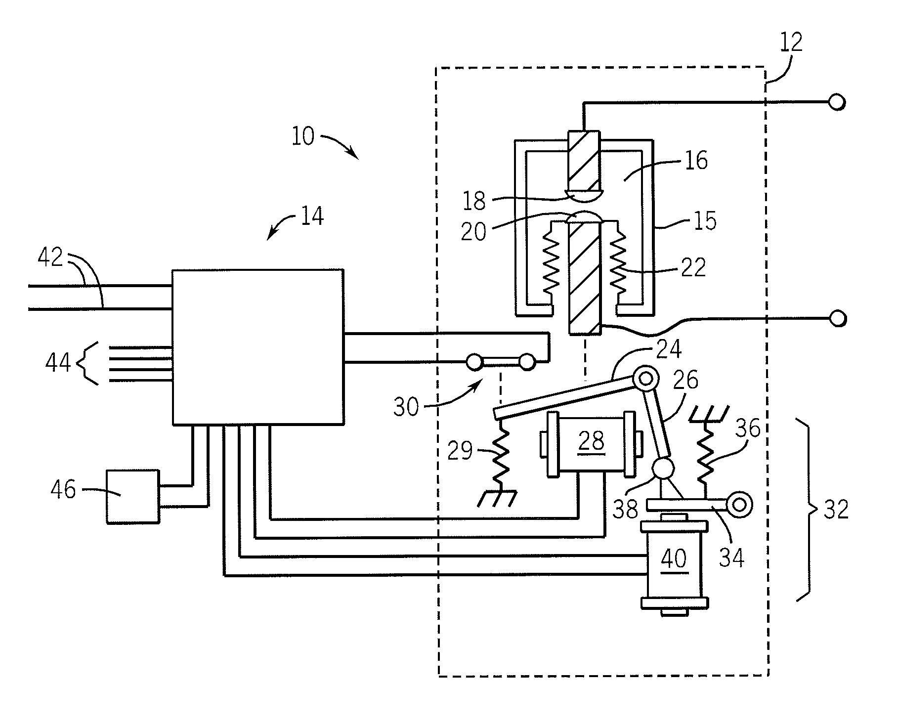
[0033]Referring now to FIG. 1, a vacuum contactor system 10, providing an example electromechanical switch system suitable for use with the present invention, includes a vacuum contactor 12 and a vacuum contactor controller 14.

[0034]As is generally understood in the art, the vacuum contactor 12 may include one or more vacuum bottles 15 providing a sealed evacuated chamber 16. Within the chamber 16 are two contacts: a stationary contact 18 fixed with respect to the vacuum bottle 15, and a movable contact 20 attached to the vacuum bottle 15 by means of a bellows 22.

[0035]The bellows 22 allows axial motion of the movable contact 20 toward and away from the stationary contact 18 under the influence of a pivoting armature 24 attached to the movable contact 20 through a biasing spring (not shown).

[0036]The armature 24 is raised or lowered by attraction between an armature tab 26 and a pole of a first electromagnet 28. In operation, the armature 24 is moved to a lowered position, separatin...


PUM


Abstract

A controller for a vacuum contactor or the like measures barometric pressure and provides a short impedance characterizing pulse to the coils of the vacuum contactor coils to assess proper operating conditions of the coils and to check for coil or sensor faults.

Description

CROSS-REFERENCE TO RELATED APPLICATIONSSTATEMENT REGARDING FEDERALLY SPONSORED RESEARCH OR DEVELOPMENTBACKGROUND OF THE INVENTION[0001]The present invention relates to electromagnetically controlled switches, such as relays and contactors, and in particular to an improved controller for vacuum contactors.[0002]Vacuum contactors are electrically controlled switches used for interrupting high power circuits. In a vacuum contactor, a pair of contacts are enclosed inside a vacuum-tight bottle. One of the contacts is fixed to an end of the bottle and the other contact may be moved by means of a bellows toward and away from the fixed contact under the influence of an electrical solenoid. The vacuum surrounding the contacts helps suppress an arc formed when a circuit is interrupted.[0003]“Electrically-held” vacuum contactors, as the name suggests, hold the contacts in a closed position by continuously applying a holding current applied to the electrical solenoid. Typically this holding cur...

Claims


Application Information

Patent Timeline
Patent Type & Authority Patents(United States)
IPC IPC(8): H01H47/00G01R31/72
CPCH01H33/666H01H47/00H01H47/02H01F7/1844G01R31/3274G01R31/06H01H2047/009G01R31/72
Inventor MACLENNAN, DAVID SCOTT S.DRAKE, REGINALD ALBERT A.
Owner ROCKWELL AUTOMATION TECH
Learn More