High voltage stable cathode for x-ray tube

a cathode and high voltage technology, applied in the direction of discharge tube main electrodes, instruments, non-electron-emitting electrode materials, etc., can solve the problems of large transverse section removed from the cup, high electric field stress, undesirable consequences

Inactive Publication Date: 2009-08-18
GENERAL ELECTRIC CO
View PDF13 Cites 3 Cited by
  • Summary
  • Abstract
  • Description
  • Claims
  • Application Information

AI Technical Summary

Problems solved by technology

The use of common machining techniques, however, tends to result in a large transverse section removed from the cup.
These sharp features lead to high electric field stress and undesirable consequences of high voltage stability issues.
This approach, however, introduces an increase in cost due to additional part manufacturing and an increase in complexity of the cathode assembly.

Method used


Image

  • High voltage stable cathode for x-ray tube
  • High voltage stable cathode for x-ray tube
  • High voltage stable cathode for x-ray tube

Examples


Embodiment Construction

)

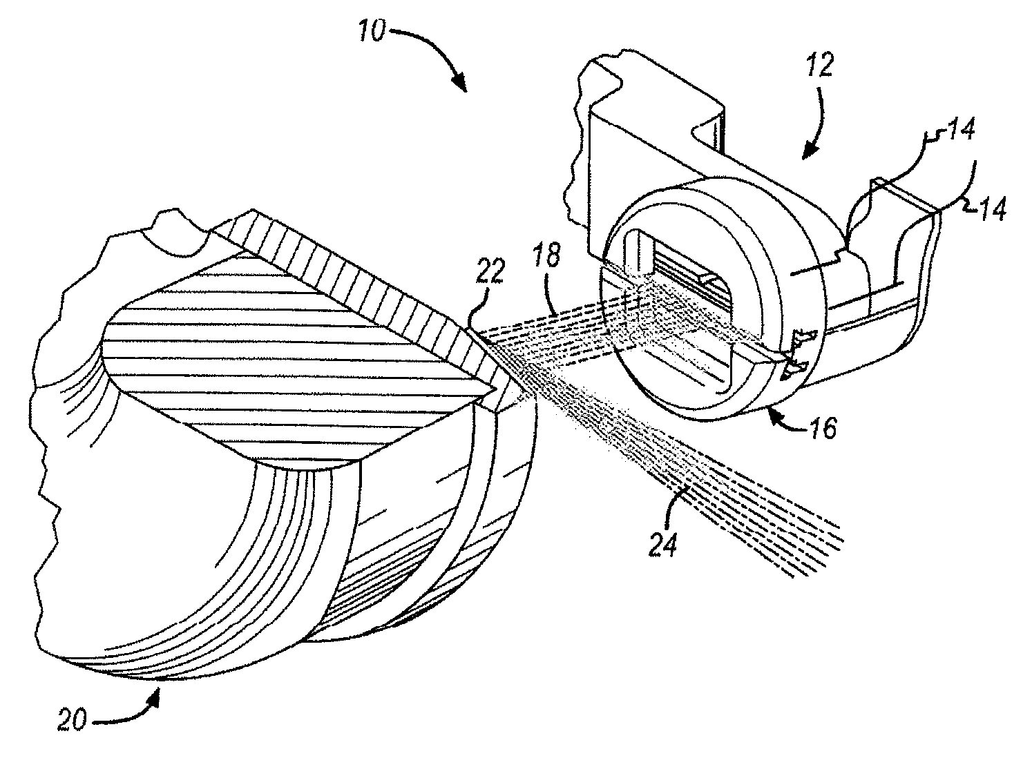
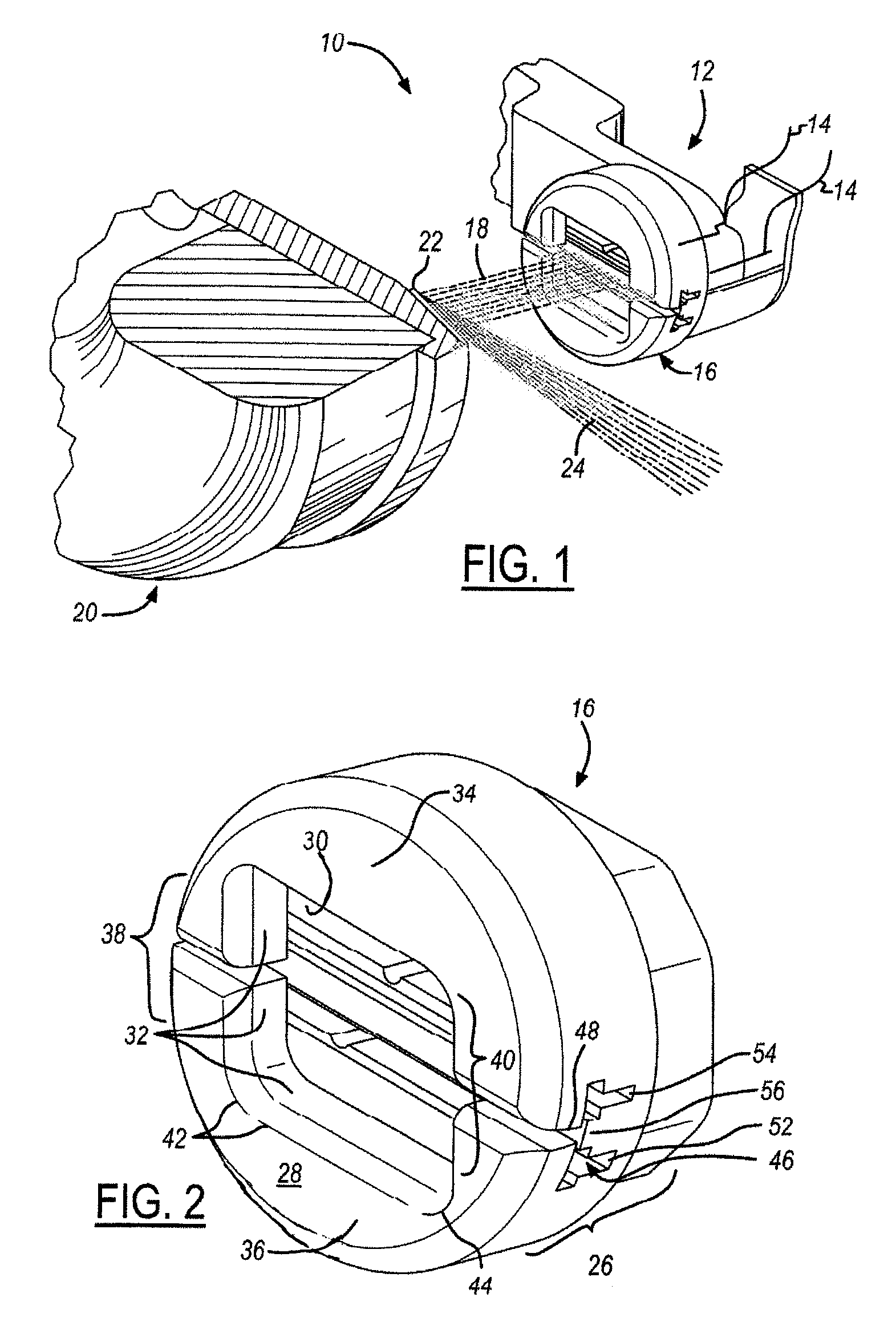
[0014]Referring now to FIG. 1, which is an illustration of an x-ray tube assembly 10 in accordance with the present invention. The x-ray tube assembly 10 is preferably for medical imaging applications although a variety of applications may be adapted in light of this disclosure. The x-ray tube assembly 10 includes a cathode assembly 12 having a plurality of wire filaments 14 positioned within a cup structure 16 for the generation of an electron beam 18. The beam 18 is directed towards an anode assembly 20 wherein the beam 18 impacts a target assembly 22 for the generation of x-rays 24 as is known in the art. The target assembly 24 is preferably rotated to prevent excess heat generation.

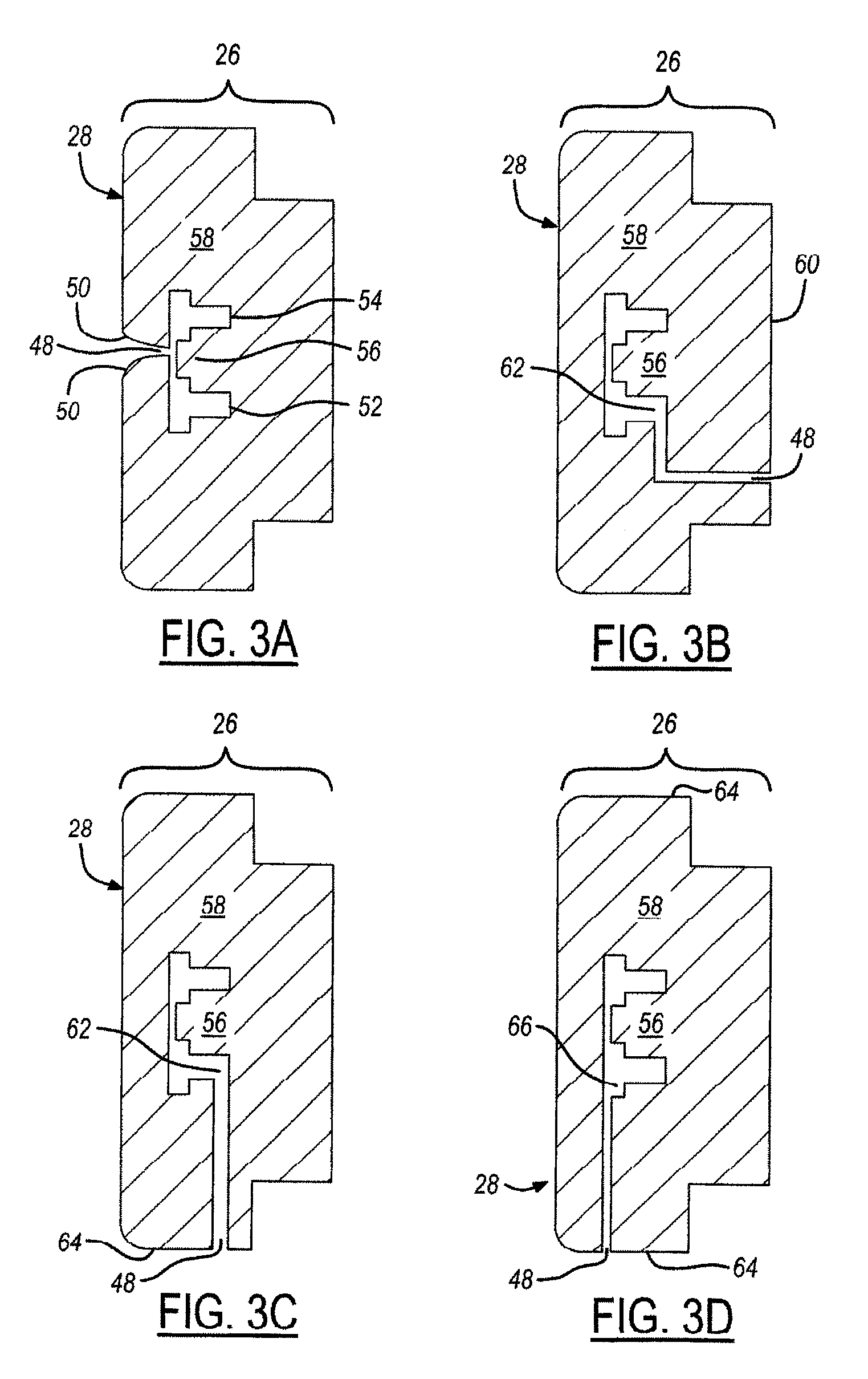
[0015]The present invention provides a unique method of producing and resultant cup structure 16 for use in the x-ray tube assembly 10 described. The cup structure 16 is comprised of a single piece cup structure 16 having a cup base portion 26 positioned below a cup emission surface portion 28 (see F...


PUM

PropertyMeasurementUnit
perimeteraaaaaaaaaa
radiused perimeteraaaaaaaaaa
electric potential distributionaaaaaaaaaa

Abstract

A method of producing a cathode for use in an x-ray tube assembly is provided including machining an emission aperture into a cup emission surface portion of a cup structure. The cup structure is comprised of a cup base portion opposite the cup emissions surface portion. Electro-discharge machining is used to form an electro-discharge machining slot into the cup structure to provide access to the interior of the cup structure. Electro-discharge machining is used to form a transverse coil chamber within the interior by way of the electro-discharge machining slot such that the transverse coil chamber is formed between the cup base portion and the cup emissions surface portion while retaining an essentially contiguous emissions surface perimeter surrounding the emission aperture.

Description

TECHNICAL FIELD[0001]The present invention relates generally to a cathode for use in an x-ray tube assembly and more particularly to a method for electro-discharge machining a cathode for use in an x-ray tube assembly.BACKGROUND OF THE INVENTION[0002]Existing medical x-ray tube assemblies include a cathode assembly having an emitter and a cup. The cathode assembly is orientated to face an x-ray tube anode, or target, which is typically a planar metal or composite structure. The space between the cathode and the anode is evacuated.[0003]A concern with existing cathode designs is that the emitter, often a helically coiled tungsten wire filament, tends to be large and electrons are emitted radially outward from all side surfaces of the filament surface. The filaments are therefore positioned within a cup that is designed to produce a tailored electric potential distribution in the vacuum such that all electron trajectories are redirected from the initial divergent motion toward a focal...

Claims


Application Information

Patent Timeline
Patent Type & Authority Patents(United States)
IPC IPC(8): H01J19/42
CPCH01J1/13H01J35/06H01J9/04Y10T29/49204H01J35/066
Inventor LEMAITRE, SERGIO
Owner GENERAL ELECTRIC CO
Why Eureka
Try Eureka