
Method and system for feedback and control of a luminaire

a technology of digital control and feedback, applied in the direction of power management, lighting and heating equipment, instruments, etc., can solve the problems of resolution, resolution, and high cost of the microcontroller, and achieve the effect of control system, and improving the accuracy of the measuremen

Active Publication Date: 2009-08-11
SIGNIFY HLDG BV
View PDF25 Cites 217 Cited by
  • Summary
  • Abstract
  • Description
  • Claims
  • Application Information

AI Technical Summary

Benefits of technology

[0030]In accordance with another aspect of the invention, there is provided a method for controlling a luminaire including one or more light-emitting elements in one or more colours, each of the one or more light-emitting elements supplied with electrical current to produce light of desired chromaticity and luminous flux under operating conditions, the method comprising the steps of: sensing predetermined fractions of light emitted by the luminaire in each of the one or more colours providing one or more sensed colour signals; processing each of the one or more sensed colour signals thereby determining one or more filtered colour signals; transforming the one or more filtered colour signals directly into control signals representative of the desired chromaticity and luminous flux; and adjusting electrical current supplied to each of the one or more light-emitting elements based on the control signals, wherein the step of adjusting is performed without perceivable visual flicker or momentary chromaticity shifts.

Problems solved by technology

A disadvantage of digital control is that the human visual system is extraordinarily sensitive to small but sudden changes in perceived brightness of illuminated surfaces, as shown for example by M. Rea, Ed., 2000, IESNA Lighting Handbook, Ninth Edition, New York, N.Y., Illuminating Engineering Society of North America, p.
Unfortunately, most commercially available microcontrollers with integrated PWM modules provide a maximum of 10-bit resolution.
Commercially-available PWM integrated circuits are available with 12-bit and greater resolution, but they are expensive in comparison with the microcontrollers they are designed to be connected to.
Unfortunately, commercially available microcontrollers with integrated analog-to-digital converter (ADC) modules provide a maximum of 10-bit resolution.
Commercially-available ADC integrated circuits are available with 12-bit and greater resolution, but they are expensive in comparison with the microcontrollers they are designed to be connected to.
24-26, this is “almost impossible for a simple microcontroller” to achieve.
In addition, lifetime testing of LEDs has shown that continuous operation of LEDs using low frequency PWM with less than 100% duty factor can impose severe and repetitive thermal stresses on LED dies, which typically have thermal time constants of 10 milliseconds.
Unfortunately, a minimum PWM frequency of about 25 kHz and a PWM resolution of 12 bits require a PWM clock frequency of about 100 MHz, which is almost impossible to achieve with commercially available microcontrollers.
This process generally results in a residual ripple current due to incomplete filtering, and whose magnitude is dependent upon the power supply load presented by the LED drive circuitry.
If the filtering is insufficient, the luminous flux output of the LEDs may vary according to twice the AC line frequency and present visual flicker to an observer.
This requirement can be difficult to achieve with luminaires having a plurality of colour LEDs, for example red, green, and blue LEDs or warm white, green, and blue LEDs, as the luminous flux outputs and dominant wavelengths of the LEDs are in general dependent on the LED junction temperatures, which are in turn dependent on the drive currents.
These may result in a nonlinear and time-dependent relationship between LED drive currents and luminous flux outputs as the LED-based luminaire is dimmed, so that the chromaticity of the luminaire is interdependent upon the time-varying LED drive currents and junction temperatures.
These undesirable visual effects may persist for several seconds until the feedback loop settles to its new equilibrium state.
While an optical feedback loop can compensate for changes in shifts in luminous flux output and chromaticity of LED-based luminaires with a plurality of colour LEDs or colour and white light LEDs, it cannot compensate for changes in sensor responsivities.
It is however an analog control system, and as such does not have a practical means to provide for example square law dimming, nor does it consider multiple interdependent colour channels.
However, it does not address the issues of sensor and digital controller resolution or PWM frequency.
It also does not consider the need to sample the sensors at a sufficiently high rate such that the luminaire chromaticity remains perceptually constant when its luminous flux output is suddenly changed, and it requires complex mathematical calculations to convert the sensor inputs to LED driver outputs that are difficult to implement in a high-speed digital feedback loop.
It does however not consider the need to sample the sensors at a sufficiently high rate such that the luminaire chromaticity remains perceptually constant when its luminous flux output is suddenly changed, and it requires complex mathematical calculations to convert the sensor inputs to LED driver outputs that are difficult to implement in a high-speed digital feedback loop.
This system again however does not address the issues of sensor resolution and temperature dependencies.
It also requires the use of memory-intensive lookup tables whose values must be predetermined for specific LEDs, and consequently it is not responsive to temperature-dependent changes in dominant wavelength or LED manufacturing tolerances.

Method used


Image

  • Method and system for feedback and control of a luminaire
  • Method and system for feedback and control of a luminaire
  • Method and system for feedback and control of a luminaire

Examples


example 1

Solid-State Lighting Luminaire

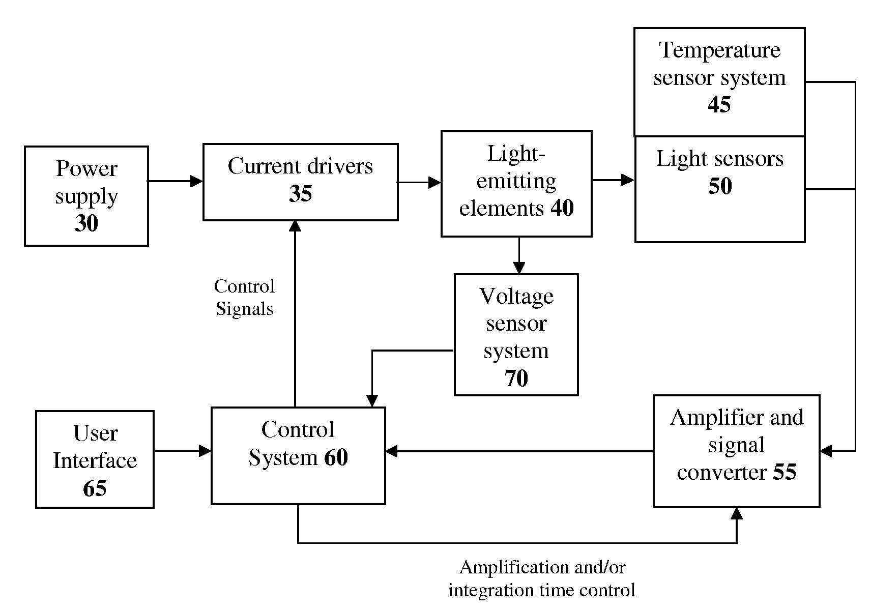
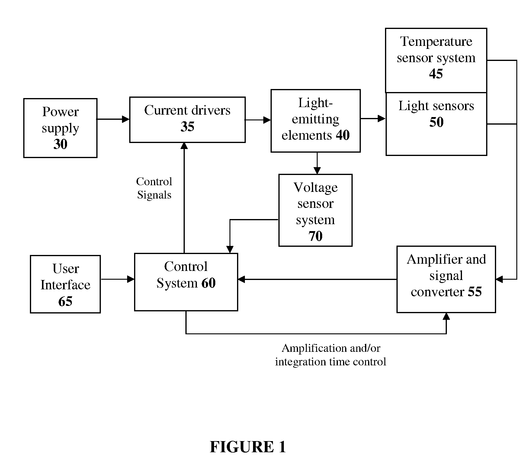
[0135]According to one embodiment of the present invention a solid-state lighting luminaire can be configured as illustrated in FIG. 1, wherein extended pulse width modulation as defined above is implemented in the control system 60 using the extended pulse code modulation method as illustrated FIGS. 15 to 17. This extended pulse code modulation method can be implemented in firmware on a commercial microcontroller which can form part of the control system 60. The light sensors 50 are broadband sensors and are associated with specific filters enabling the sensors to detect light in one predetermined wavelength region, for example red, green and blue regions. This format of light sensors are integrated with associated amplification stages as illustrated in FIG. 6. Additional functions may also be implemented, such as for example monitoring of voltage sensors 70 and temperature sensors 45 by the control system. This information is used by the control syste...

example 2

Solid-State Lighting Luminaire

[0136]According to one embodiment of the present invention a solid-state lighting luminaire can be configured as illustrated in FIG. 1, wherein extended pulse width modulation as defined above is implemented in the control system 60 using the extended pulse width modulation method as illustrated FIGS. 12 to 14. This extended pulse width modulation method can be implemented in firmware on a commercial microcontroller which can form part of the control system 60. The light sensors 50 are broadband sensors and are associated with specific filters enabling the sensors to detect light in one predetermined wavelength region, for example red, green and blue regions. This format of light sensors are integrated with associated amplification stages as illustrated in FIG. 6. Additional functions may also be implemented, such as for example monitoring of voltage sensors 70 and temperature sensors 45 by the control system. This information is used by the control sys...

example 3

Solid-State Lighting Luminaire

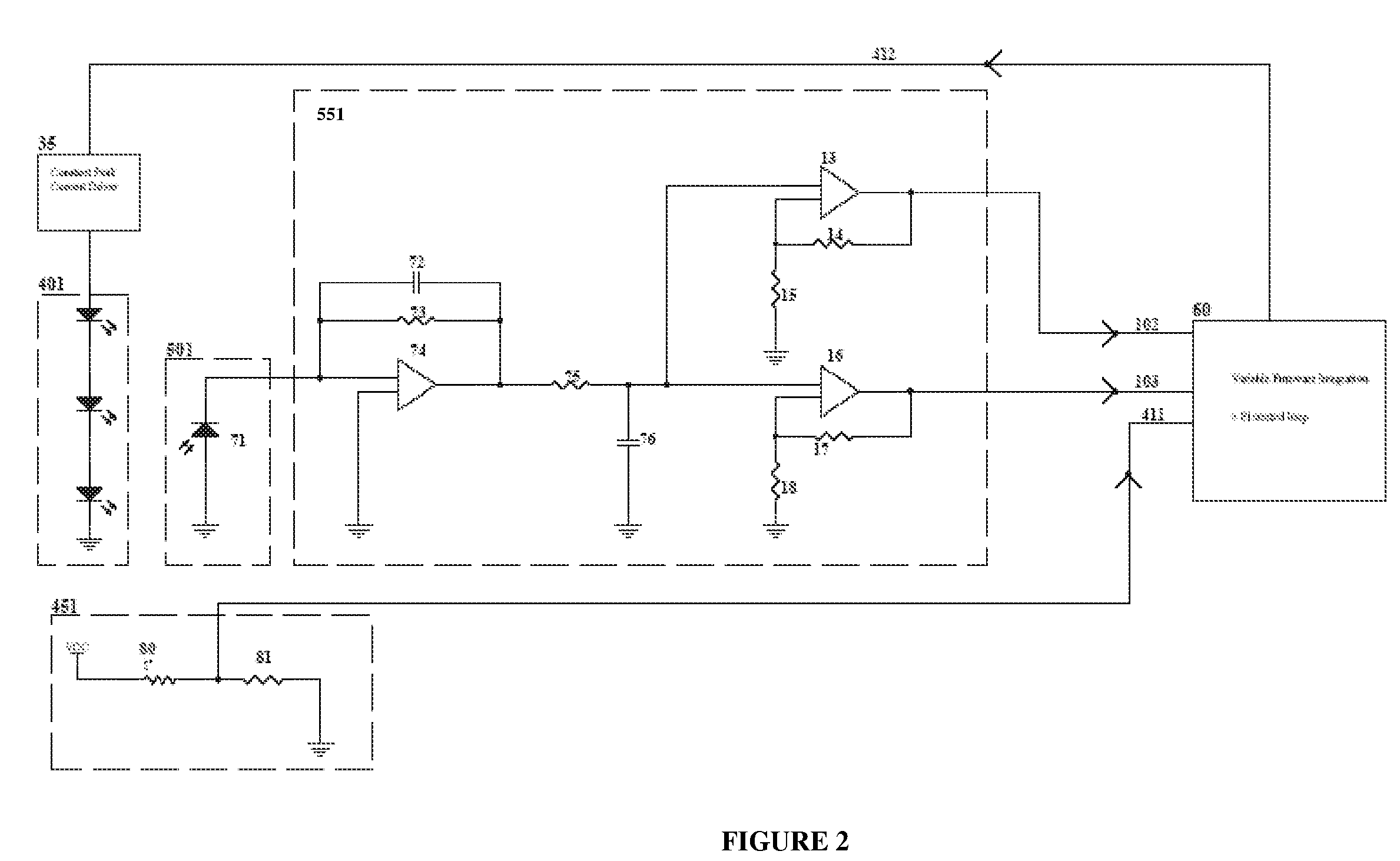
[0137]According to one embodiment of the present invention a solid-state lighting luminaire can be configured as illustrated in FIG. 1, wherein extended pulse width modulation as defined above is implemented in the control system 60 using the extended pulse code modulation method as illustrated FIGS. 15 to 17. This extended pulse code modulation method can be implemented in firmware on a commercial microcontroller which can form part of the control system 60. The light sensors 50 are narrow band sensors which detect light in one predetermined wavelength region, for example red, green and blue regions. These light sensors are integrated with associated amplification stages as illustrated in FIG. 2. Additional functions may also be implemented, such as for example monitoring of voltage sensors 70 and temperature sensors 45 by the control system. This information is used by the control system for feedback and feedforward control which is implemented in fir...


PUM


Abstract

A method and system for controlling the chromaticity and luminous flux output of a digitally controlled luminaire. The luminaire includes one or more light-emitting elements and one or more light sensors for providing optical feedback, which is filtered to remove undesired frequencies. The method and system employs a control system which can sample the filtered signals from the light sensors according to a predetermined feedback sampling frequency scheme, wherein this scheme is specifically configured to provide sufficient iterations of the feedback loop to be performed for adjustment of the chromaticity and luminous flux output of the light-emitting elements, without perceptible visual flicker or momentary chromaticity shifts.

Description

FIELD OF THE INVENTION[0001]The present invention pertains to a method and system for feedback and control of digitally controlled luminaries.BACKGROUND[0002]Existing commercially available light-emitting diodes (LEDs), including solid-state LEDs, organic light-emitting diodes (OLEDs), polymer light-emitting diodes (PLEDs), and electroluminescent devices, can be manufactured to generate light of different chromaticity with high electro-optical conversion efficiency. Single-colour and white light-emitting diodes can be used, for example, in luminaries whose luminous flux output and chromaticity can be digitally controlled.[0003]The luminous flux output and chromaticity of LEDs are generally dependent on LED junction temperature, dominant wavelength shifts, manufacturing tolerances (especially dominant wavelength and luminous intensity binning), and device ageing. These dependencies are further compounded by their use in luminaires, where ambient operating temperatures and power suppl...

Claims


Application Information

Patent Timeline
Patent Type & Authority Patents(United States)
IPC IPC(8): G05F1/00H04W48/16H04W52/02H04W64/00H05B44/00
CPCH05B33/0818H05B33/0854H05B33/0857H05B33/0869H05B33/0872H05B33/0851G09G3/2014G09G2320/0247G09G2330/028Y02B20/346H05B45/22H05B45/24H05B45/28H05B45/37Y02B20/30
Inventor ASHDOWN, IANROBINSON, SHANE P.
Owner SIGNIFY HLDG BV
Learn More