Electrical connector wire guide with hinged cam lock

a technology of hinged cam lock and wire guide, which is applied in the direction of coupling/disassembly parts, electrical devices, and connection of coupling devices, etc., and can solve problems such as loose and tenuous mechanical connections, wire guides are susceptible to damage, and are prone to accidental disengagement from connectors

Inactive Publication Date: 2009-08-04
TE CONNECTIVITY CORP
View PDF3 Cites 6 Cited by
  • Summary
  • Abstract
  • Description
  • Claims
  • Application Information

AI Technical Summary

Problems solved by technology

Such wire guides, while easy to install, are prone to accidental disengagement from the connector during the original installation of the connector or during maintenance.
Additionally, the flexible plastic parts are necessarily thin and lack sufficient support for securely attaching the wire guide to the connector housing resulting in a loose and tenuous mechanical connection.
Such wire guides are susceptible to damage when their removal is attempted for maintenance of the connector.

Method used


Image

  • Electrical connector wire guide with hinged cam lock
  • Electrical connector wire guide with hinged cam lock
  • Electrical connector wire guide with hinged cam lock

Examples


Embodiment Construction

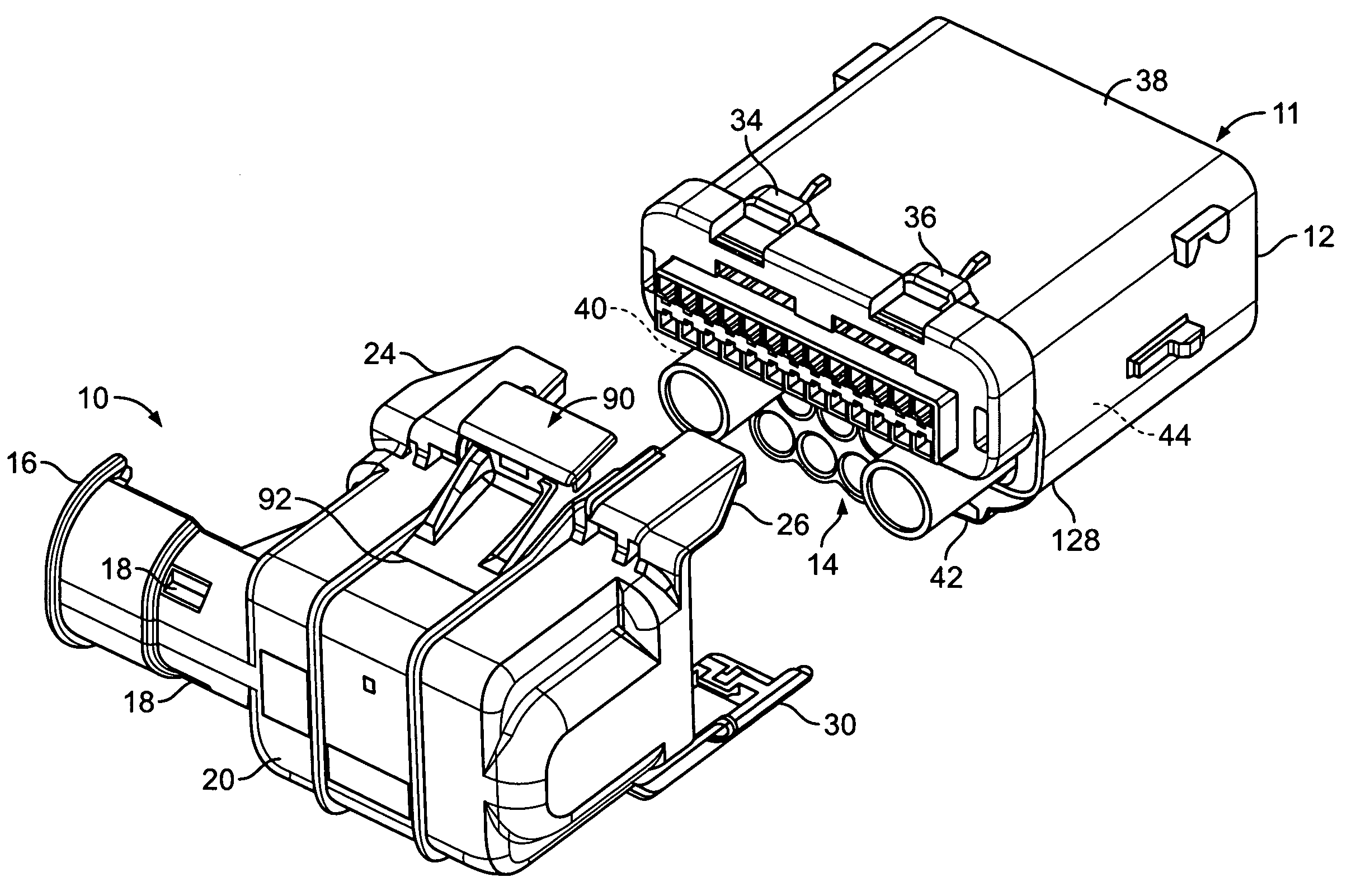
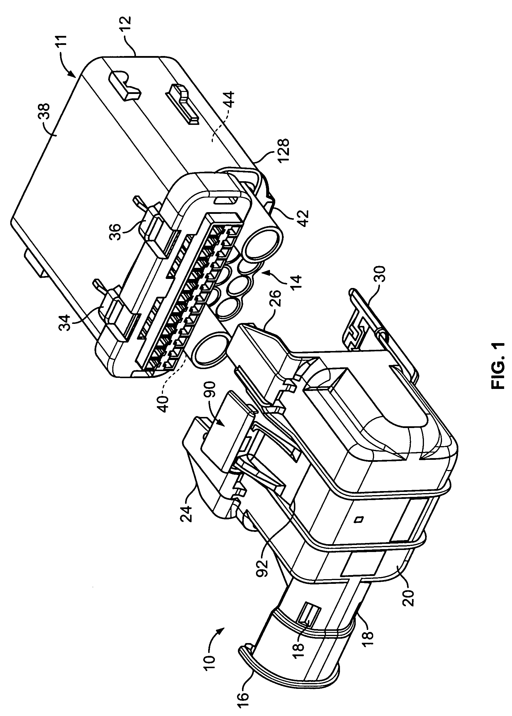
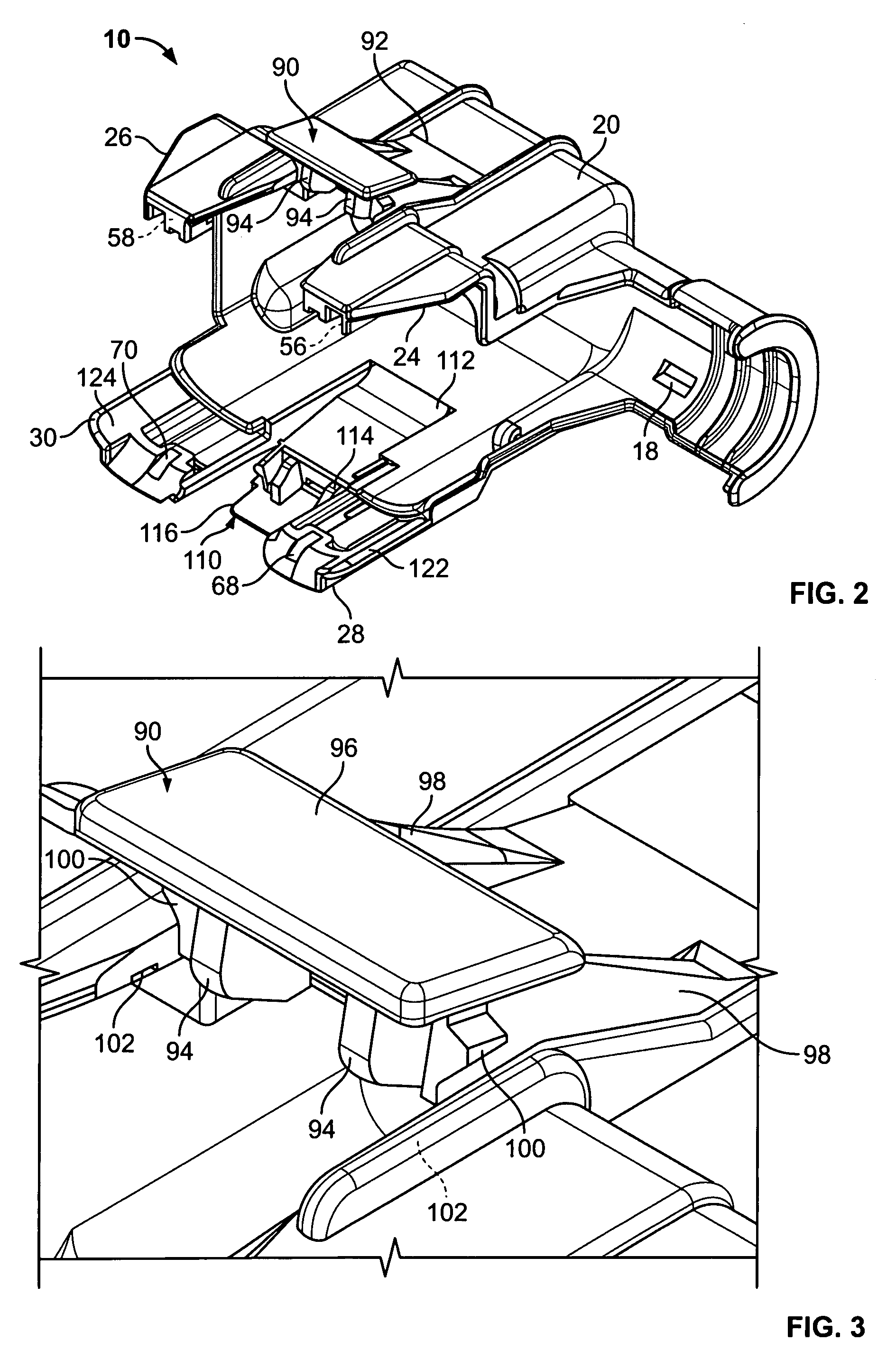
[0013]There is shown in FIG. 1 a wire guide 10 and a mating electrical connector 11 having a housing 12. The connector housing includes a wire terminating end 14 to which a quantity of wires (not shown) may be terminated. The terminated wires are normally grouped into a bundle and directed off to one side. The wire guide 10 includes a wire exit end 16 extending from and integrally molded to a body 20. The wire guide 10 is arranged to mate with the connector housing so that the wire bundle is directed through and partially surrounded by the wire exit end 16. Two tie slots 18 are arranged in the wire exit end permitting bundle ties to be inserted therethrough and wrapped around both the wire bundle and the wire exit end 16 thereby tightly securing the wire bundle to the wire guide 10.

[0014]The wire guide 10 includes a first pair of guide arms 24 and 26 extending from one side thereof and a second pair of guide arms 28 and 30 extending from an opposite side thereof, as best seen in FIG...


PUM


Abstract

A wire guide (10) is disclosed that is removably attachable to an electrical connector (11) for guiding wires terminated thereto. Guide arms (24, 26, 28, 30) extend from a body 20 and include alignment members (122, 124) for engaging alignment features (126, 128) on the connector during assembly. The guide arms include catch fingers (56, 58, 68, 70) that engage catch features (34, 36, 40, 42) on the connector. Two hinged cam locks (90, 110), each being arranged between respective pairs of guide arms, are manually manipulated to cause the catch fingers to engage their respective catch features thereby positively securing the wire guide to the connector.

Description

[0001]The present invention relates to wire guides removably attachable to an electrical connector for guiding the wires connected thereto into a neat bundle and more particularly to wire guides having an improved alignment and locking mechanism for securing the wire guide to the connector.BACKGROUND OF THE INVENTION[0002]Wire guides for electrical connectors are often made of a plastic insulating material and are arranged to attach to a connector housing so that the wires terminated in the housing are guided away from their termination points and into a neat bundle. In many cases the wire guide also serves as a strain relief for the wires. Prior art wire guides are typically attach to their respective connector housings by detents, flexible plastic parts that engage features on the housing, or other mechanisms that easily snap into place. Such wire guides, while easy to install, are prone to accidental disengagement from the connector during the original installation of the connect...

Claims


Application Information

Patent Timeline
Patent Type & Authority Patents(United States)
IPC IPC(8): H01R13/62
CPCH01R13/506H01R13/62905H01R13/6271H01R13/567H01R13/501
Inventor KINSEY, JR., FORREST IRVING
Owner TE CONNECTIVITY CORP
Why Eureka
Try Eureka