
Modular shade system with solar tracking panels

a solar tracking and module technology, applied in the safety of solar heat collectors, lighting and heating equipment, electric generators, etc., can solve the problems of scarce or inexistent open land for pv installation

Active Publication Date: 2009-07-07
TOTALENERGIES ONETECH
View PDF58 Cites 84 Cited by
  • Summary
  • Abstract
  • Description
  • Claims
  • Application Information

AI Technical Summary

Problems solved by technology

Many times in areas where PV is most economically attractive, open land for PV installation is scarce or nonexistent.

Method used


Image

  • Modular shade system with solar tracking panels
  • Modular shade system with solar tracking panels
  • Modular shade system with solar tracking panels

Examples


Embodiment Construction

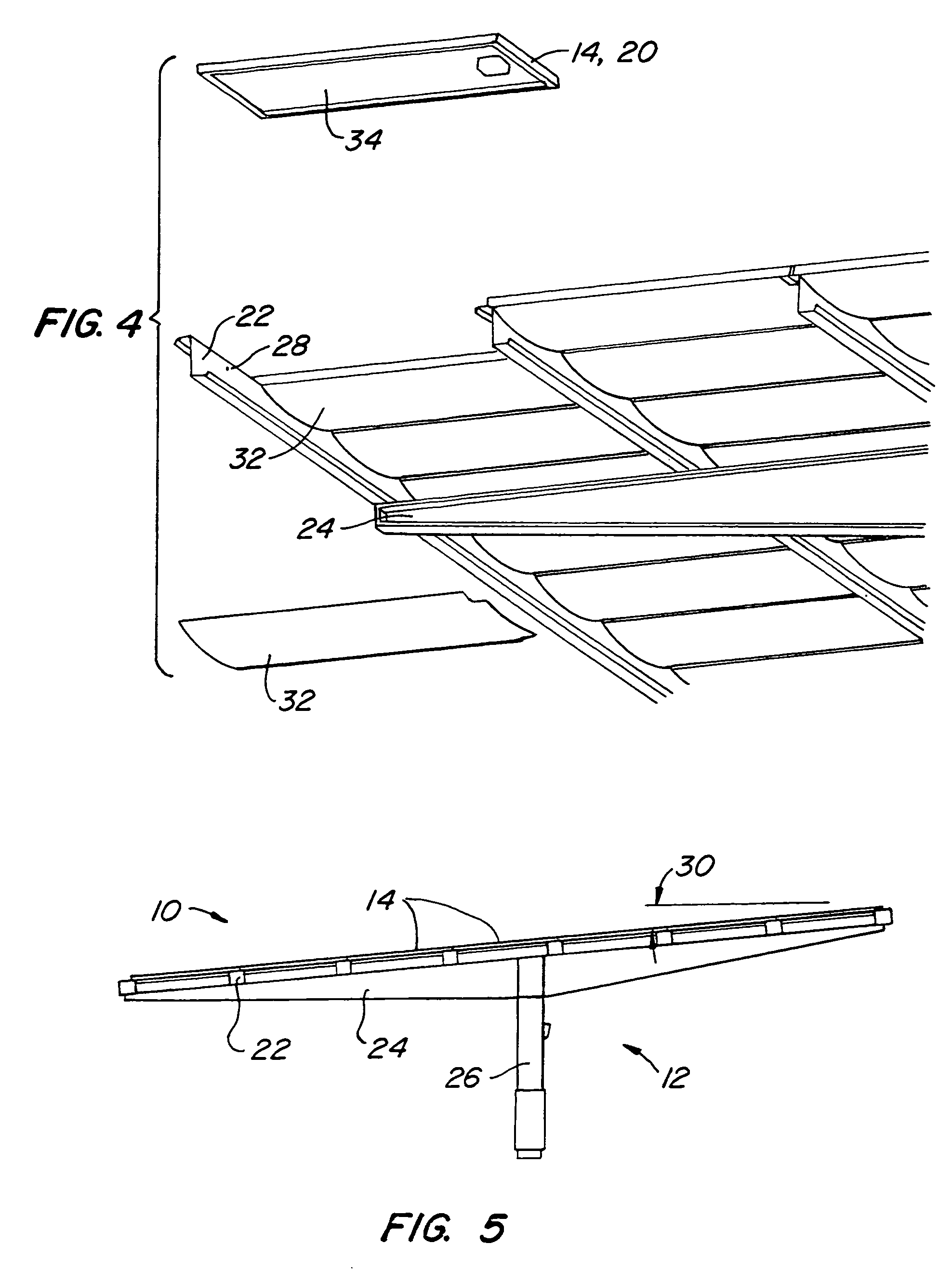
[0019]FIGS. 1-5 illustrate the basic components of shade system 10. Shade system 10 comprises a support structure 12, shown best in FIGS. 3 and 4, to which an array of modular panels 14 are mounted. In one embodiment the center row 16 of modular panels 14 are tinted, transparent panels 18 provided to create an illuminated walkway along the length of shade system 10. The tinting of transparent panels 18, such as red, also provides a distinctive, aesthetically pleasing aspect to the shade system. In this embodiment the remainder of modular panels 14 are PV panels 20 so that shade system also acts as a source of electricity. Electricity could be used for a variety of purposes including charging batteries, creating hydrogen from water, or after being transformed into alternating current, fed into the commercial electrical grid. The modular panels 14 could also include other types of modular structures such as planter modules used for growing plants on the top of shade system 10, skyligh...


PUM


Abstract

A modular shade system with solar tracking panels includes a series of generally North-South oriented, spaced apart torque tubes, each torque tube having an axis, a series of panels mounted to at least some of the torque tubes to create spaced-apart rows of panels along the torque tubes, at least some of the panels being solar collector panels. The system also includes a shade structure, positioned at a selected location between selected ones of the torque tubes and above the support surface so to provide an enhanced shaded region thereunder, and a support structure. The support structure includes a first mounting assembly mounting each torque tube above the support surface for rotation about the axis of each torque tube and a second mounting assembly supporting the shade structure at the selected location. The system further comprises a tilting assembly selectively rotating each torque tube about its axis.

Description

CROSS-REFERENCE TO OTHER APPLICATIONS[0001]This application claims the benefit of U.S. provisional patent application No. 60 / 453,637 filed on 10 Mar. 2003 and U.S. provisional patent application No. 60 / 517,574 filed on 5 Nov. 2003. This application is related to U.S. design patent application Ser. No. 29 / 177,528 filed on 10 Mar. 2003. This application is also related to U.S. patent application Ser. No. 10 / 796,299,entitled Modular Shade System, filed on the same day as this application.BACKGROUND OF THE INVENTION[0002]To improve the quality and economic value of outdoor spaces, it is desirable to develop means to provide low-cost, multi-use structures, to facilitate such things as mounting for electricity generating PV modules, shade for cars, shade for outdoor activities, agriculture, aquaculture, and to promote other purposes and events. Ancillary advantages from green roofs, also called vegetative roof coverings or eco-roofs, include controlling water runoff and reducing subsequen...

Claims


Application Information

Patent Timeline
Patent Type & Authority Patents(United States)
IPC IPC(8): E04B7/02H01L25/00H02N6/00E04D13/18F24J2/04F24J2/54
CPCF24J2/04F24J2/045F24J2/541F24J2/5232F24J2002/5468Y02B10/12F24J2/4607Y02B10/20Y02E10/44Y02E10/47Y02B10/14F24S10/00F24S40/00F24S20/67F24S30/425F24S25/12F24S2030/136Y02B10/10Y02E10/50H02S20/10
Inventor SHINGLETON, JEFFERSON G.DINWOODIE, THOMAS L.MASCOLO, GIANLUIGI
Owner TOTALENERGIES ONETECH
Learn More