
Irradiation direction controller and leveling angle setting method of vehicle lamp

a technology of irradiation direction and controller, which is applied in the direction of process and machine control, instruments, lighting and heating apparatus, etc., can solve the problems of preventing precise auto-leveling, affecting the accuracy of vehicle irradiation, and insufficient front irradiation of vehicles, so as to ensure flexibility in vehicle assembly and precise aiming adjustment

Active Publication Date: 2009-06-23
KOITO MFG CO LTD
View PDF11 Cites 8 Cited by
  • Summary
  • Abstract
  • Description
  • Claims
  • Application Information

AI Technical Summary

Benefits of technology

[0013]In accordance with one or more embodiments of the present invention, an irradiation direction controller for a vehicle lamp is capable of performing an aiming adjustment prior to a vehicle height value initialization.
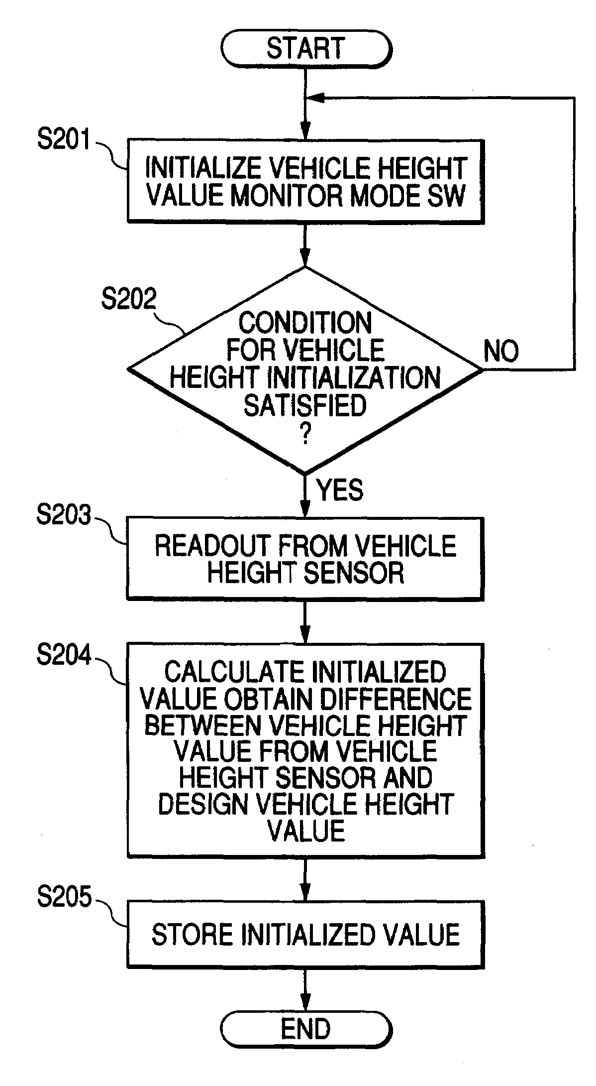
[0019]In accordance with one or more embodiments of the present invention, when the vehicle height value obtained from a vehicle height sensor is initialized, precise aiming adjustment as before is possible. In case the vehicle height value is not initialized, leveling adjustment based on a predetermined value followed by aiming adjustment and subsequent initialization of the vehicle height value cancels an error in the aiming adjustment thus providing appropriate aiming adjustment. This assures flexibility in the assembly of a vehicle without using a fixed order of a vehicle height value initialization process and an aiming process.

Problems solved by technology

When the irradiation direction is set downward, front irradiation of the vehicle is insufficient.
During a mounting of the vehicle height sensor on the vehicle body, some mounting error may be occurred.
A mounting error in a vehicle height value obtained from a vehicle height sensor prevents precise auto-leveling.
The aiming adjustment of a headlamp set to an error-containing leveling angle results in inappropriate aiming adjustment.
The related-art approach cannot respond to a request for such a flexible assembly process design.

Method used


Image

  • Irradiation direction controller and leveling angle setting method of vehicle lamp
  • Irradiation direction controller and leveling angle setting method of vehicle lamp
  • Irradiation direction controller and leveling angle setting method of vehicle lamp

Examples


Embodiment Construction

[0028]Embodiments of the invention will be described with reference to the accompanying drawings.

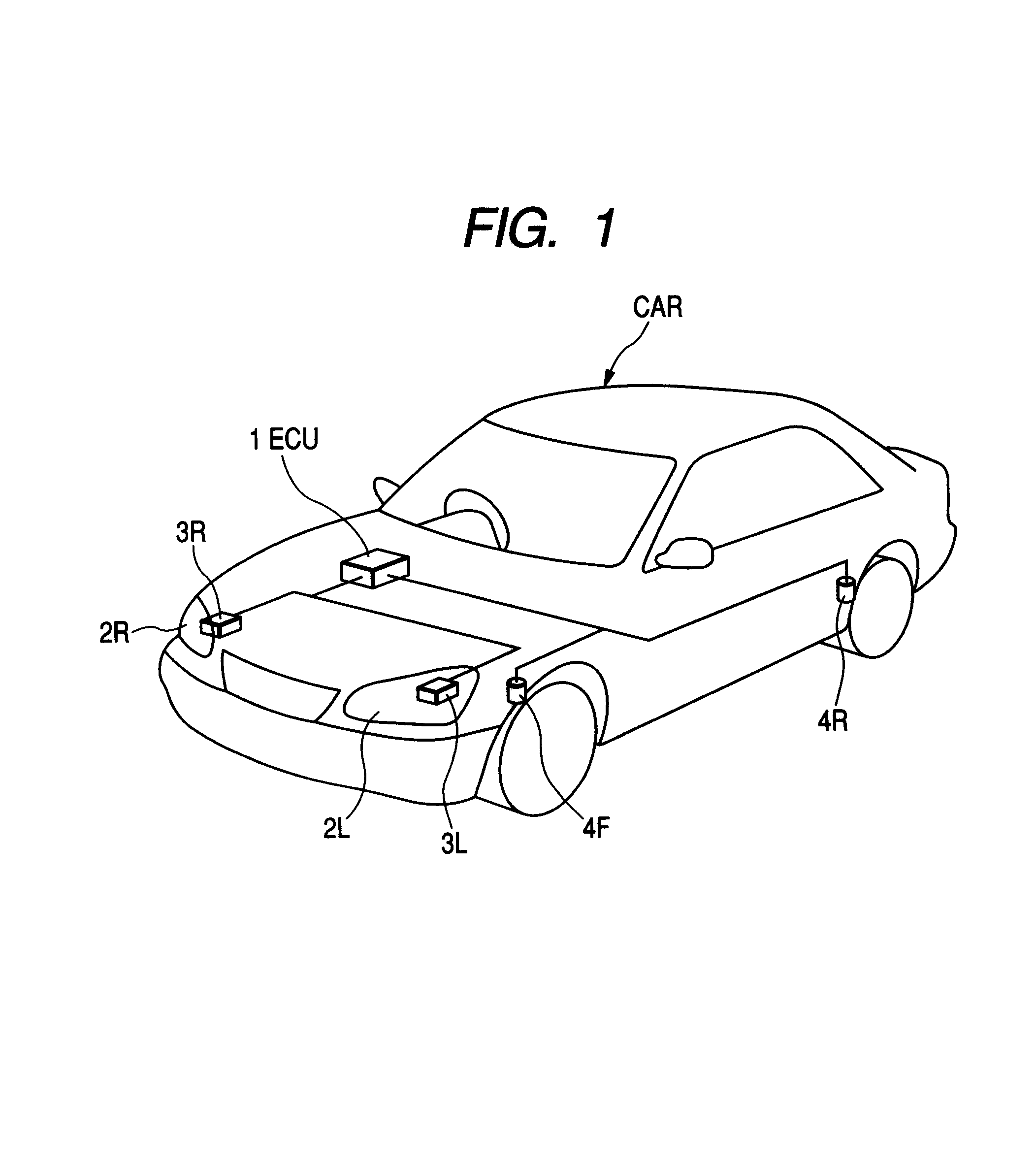
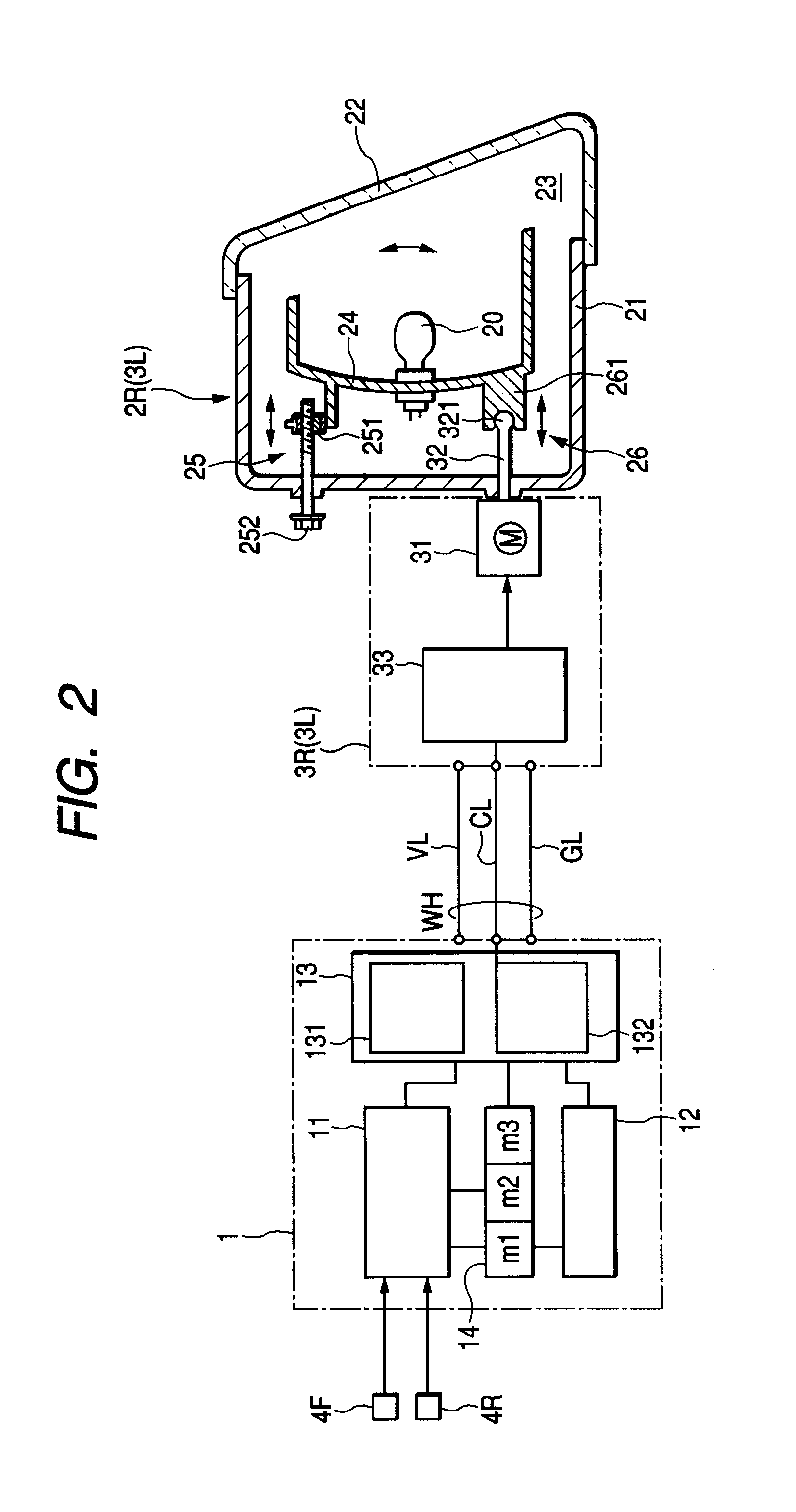
[0029]FIG. 1 is a conceptual diagram of a vehicle equipped with an irradiation direction controller. The irradiation direction controller in FIG. 1 controls the irradiation direction of a pair of headlamps 2L, 2R provided on the front left and front right sections of a vehicle CAR. The irradiation optical axis of the headlamps 2L, 2R can be controlled in avertical direction or in up-down direction with respect to the vehicle body by way of left and right actuators 3L, 3R. As a controller for the actuators 3L, 3R for making angle control of the headlamps 2L, 2R, an Electronic Control Unit (ECU) 1 incorporating a CPU is provided. Based on a change in a pitch angle, the ECU 1 controls the irradiation direction of the headlamp to constantly form a certain angle in vertical direction with respect to a road surface. Further, vehicle height sensors 4F, 4R are provided for detecting the vehicle ...


PUM


Abstract

A leveling controller (ECU) calculates a pitch angle based on a vehicle height value of a vehicle and controls an irradiation direction of a vehicle lamp. The leveling controller includes a vehicle height value initialization unit for initializing the detected vehicle height value, a determination unit for determining whether initialization by the vehicle height value initialization unit has been made, and a leveling angle setting unit for setting the leveling angle of the vehicle lamp based on the initialized vehicle height value or setting the leveling angle to a predetermined leveling angle, in accordance with the result of determination by the determination unit. An aiming device is arranged to perform aiming adjustment on the vehicle lamp in which the leveling angle is set by the leveling angle setting unit.

Description

[0001]The present application claims foreign priority based on Japanese Patent Application No. P.2004-241911, filed on Aug. 23, the contents of which are incorporated herein by reference.BACKGROUND OF THE INVENTION[0002]1. Field of the Invention[0003]The present invention relates to a controller for controlling an irradiation direction of a vehicle lamp, and in particular to an irradiation direction controller and a leveling angle setting method, for vertically controlling the irradiation direction of a headlamp in accordance with the tilt angle of the front section of the vehicle in a vertical direction with respect to a road surface.[0004]2. Related Art[0005]When a cargo loading state of a vehicle or number of passengers are changed, a deflection quantity of a spring of a suspension device supporting a vehicle body may change, and an elevation angle formed by a front of the vehicle body with respect to a road surface, that is, a vertical angle of the vehicle in a longitudinal dire...

Claims


Application Information

Patent Timeline
Patent Type & Authority Patents(United States)
IPC IPC(8): B60Q1/10
CPCB60Q1/115B60Q2300/132
Inventor ANDO, MASATAKA
Owner KOITO MFG CO LTD
Learn More