
Cleaning device for a fixing unit

a cleaning device and fixing technology, applied in the direction of instruments, electrographic process equipment, optics, etc., can solve the problems of spoilage or dirty front and rear sides of recording paper, affecting and prone to large thickness of the entire layer of unfixed developer, so as to improve the quality of recording paper image formation, remove leftover developer intensively, and improve the effect of image quality

Inactive Publication Date: 2009-06-02
SHARP KK
View PDF6 Cites 2 Cited by
  • Summary
  • Abstract
  • Description
  • Claims
  • Application Information

AI Technical Summary

Benefits of technology

[0014]A cleaning device has been developed for a fixing unit which can reliably prevent smudges on the front and rear surfaces of the recording paper by positively removing the remaining developer from the heating and pressing member of the fixing unit, to thereby improve the quality of images formed on the recording paper.

Problems solved by technology

In the case of such a color image forming apparatus, multiple colors of developer images are transferred to the recording paper (forming layers of developer images), so that the total thickness of the layers of unfixed developers is prone to be large.
When the total layer of the unfixed developers is thick as above, there may occur the problem with the conventional fixing unit that part of the developers adheres to the heat roller.
However, after a period of a certain use of the image forming apparatus, the cleaning member of the cleaning device becomes dirty with the developer hence will degrade in cleaning performance.
If this occurs, the unnecessary developer remains on the fixing rollers (heat roller and pressing roller), and part of the remaining developer may adhere to the recording paper hence spoil or dirty the front and rear sides of the recording paper.
When the remaining developer that has built up at these areas separates and drops due to some kind of impact and adheres to the recording paper, the developer is fused and fixed by heat from the heated fixing rollers, producing defects such as smudges or visible spots, etc., on the recording paper (the front and rear surfaces).
Thus, the problem of image quality degradation occurs.

Method used


Image

  • Cleaning device for a fixing unit
  • Cleaning device for a fixing unit
  • Cleaning device for a fixing unit

Examples


Embodiment Construction

[0034]Referring next the drawings shown in FIGS. 1 to 5, the embodiment of a drive control devices of drive rollers of an image forming apparatus will be described in detail.

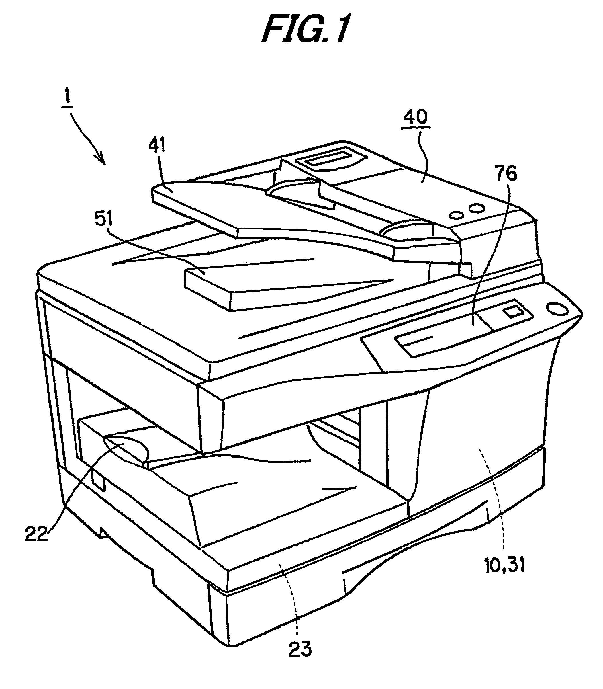
[0035]FIG. 1 shows an overall external configuration of an image forming apparatus according to the embodiment of the present invention; FIG. 2 shows the internal structure of the image forming apparatus; and FIG. 3 shows control blocks in the electric control system of the image forming apparatus. In the drawings, a reference numeral 1 designates a main apparatus body (machine body).

[0036]As shown in FIGS. 1 to 3, an original placement table 2 made of transparent glass, on which an original is placed, is provided on the top of the main apparatus body 1. A scanner portion 3 as a document reader for capturing image information of an original G is arranged under the original placement table 2.

[Scanner Portion 3]

[0037]Scanner portion 3 is composed of an original image reading unit including a first scan unit 4 and ...


PUM


Abstract

A fixing unit includes a heat roller and a pressing roller that comes in pressure contact with the heat roller, and passes the recording paper with an unfixed toner image formed thereon through the nip between the heat roller and pressing roller to thereby fix the toner image to the recording paper by applying heat and pressure thereto. A cleaning device for removing the toner remaining on the heat roller or pressing roller in the fixing unit includes cleaning rollers made of metal arranged in press-contact with the heat roller and pressing roller, the peripheral surface of the cleaning rollers being formed with projected and indented shapes to thereby remove the leftover toner appropriately.

Description

[0001]This Nonprovisional application claims priority under 35 U.S.C. § 119(a) on Patent Application No. 2005-88149 filed in Japan on 25 Mar. 2005, the entire contents of which are hereby incorporated by reference.BACKGROUND OF THE INVENTION[0002](1) Field of the Invention[0003]The present invention relates to a cleaning device for a fixing unit in an electrophotographic image forming apparatus, the fixing unit being formed of a heating member incorporating a heater and a pressing member that is put in press-contact with the heating member to fix an unfixed developer image formed on the surface of recording paper thereto by applying heat and pressure as the paper is passed through the nip between the heating member and pressing member, and more specifically, relates to a cleaning device for removing the developer remaining on the heating member and / or pressing member in the fixing unit.[0004](2) Description of the Prior Art[0005]There are known electrophotographic image forming appa...

Claims


Application Information

Patent Timeline
Patent Type & Authority Patents(United States)
IPC IPC(8): G03G15/20
CPCG03G15/2025G03G15/2028
Inventor SHINKAWA, TATSUYAYAMANAKA, TAKASHIMUKAI, KANWAKAMOTO, KOUJI
Owner SHARP KK
Learn More