
Pipe fitting and associated methods and apparatus

a technology of pipe fittings and fittings, applied in the direction of hose connections, mechanical equipment, pipe elements, etc., can solve the problems of pipe fittings that have been known to fail at the crimp, pipe fittings that fail occasionally, etc., and achieve the effect of convenient connection, advantageous compactness, and convenient twisting

Active Publication Date: 2009-05-05
CHARLOTTE PIPE & FOUNDRY
View PDF41 Cites 17 Cited by
  • Summary
  • Abstract
  • Description
  • Claims
  • Application Information

AI Technical Summary

Benefits of technology

[0012]Further to one aspect of the present invention, the metallic body of the composite fitting includes at least one spiral thread, which can be internal or external, for facilitating connection of the composite fitting to a piece of plumbing by twisting. The piece of plumbing preferably includes metallic thread(s) for mating with the thread(s) of the metallic body. The metallic body can include an outer polygonal portion for being engaged by a wrench, for facilitating the twisting.
[0013]In accordance with one aspect of the present invention, an internal stop, which is preferably annular and part of the polymeric body, protrudes into the passageway for engaging an end of the polymeric pipe, or other piece of plumbing, inserted into composite fitting, for arresting relative movement between the composite fitting and the piece of plumbing (e.g., polymeric pipe). Likewise, it is preferred for an internal or external stop, which is preferably annular and part of the metallic body, to be available for engaging an end of the metallic pipe or fitting, or other piece of plumbing, installed to the composite fitting, for arresting relative movement between the composite fitting and the piece of plumbing (e.g., metallic pipe or fitting).
[0014]In accordance with one aspect of the present invention, the composite fitting is advantageously compact as compared to comparable conventional fittings.

Problems solved by technology

Nonetheless, it is common for some of these pipe fittings to occasionally fail, since they are typically exposed to many cycles of stress caused by variations in the pressure and / or temperature of the water being supplied.
These pipe fittings have been known to fail at the crimp, because the crimping can weaken the metallic body.

Method used


Image

  • Pipe fitting and associated methods and apparatus
  • Pipe fitting and associated methods and apparatus
  • Pipe fitting and associated methods and apparatus

Examples


Embodiment Construction

[0034]The present inventions now will be described more fully hereinafter with reference to the accompanying drawings, in which some, but not all embodiments of the inventions are shown. Indeed, these inventions may be embodied in many different forms and should not be construed as limited to the embodiments set forth herein; rather, these embodiments are provided so that this disclosure will satisfy applicable legal requirements. Like numbers refer to like elements throughout.

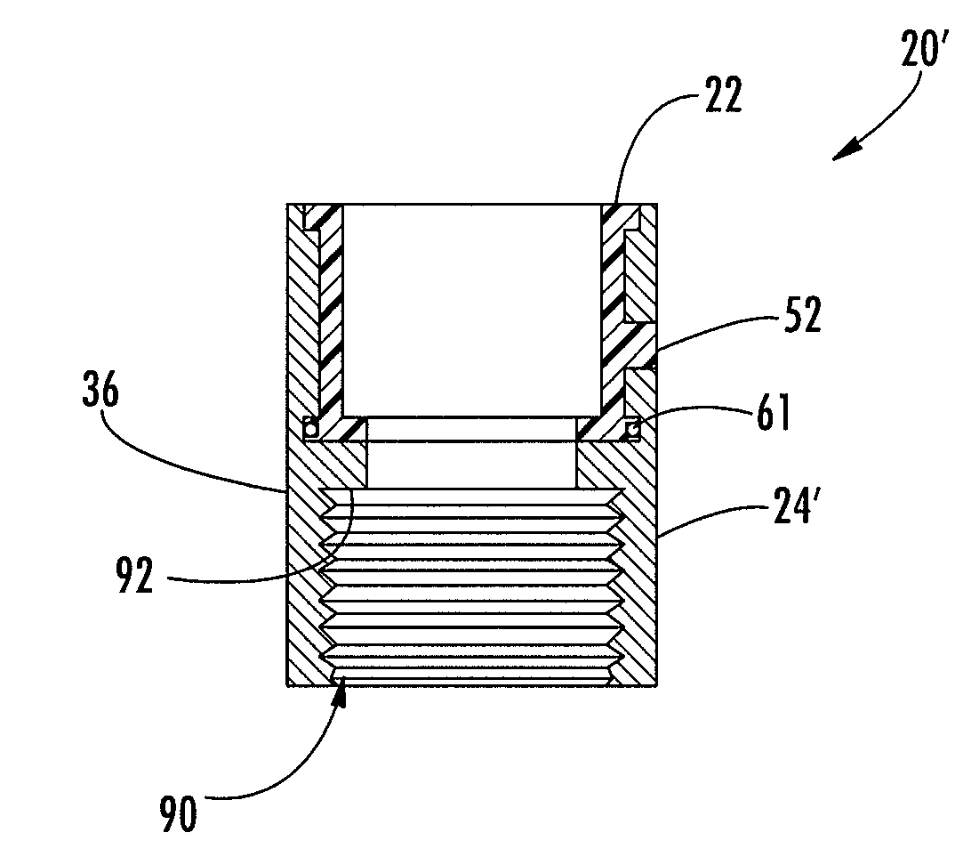
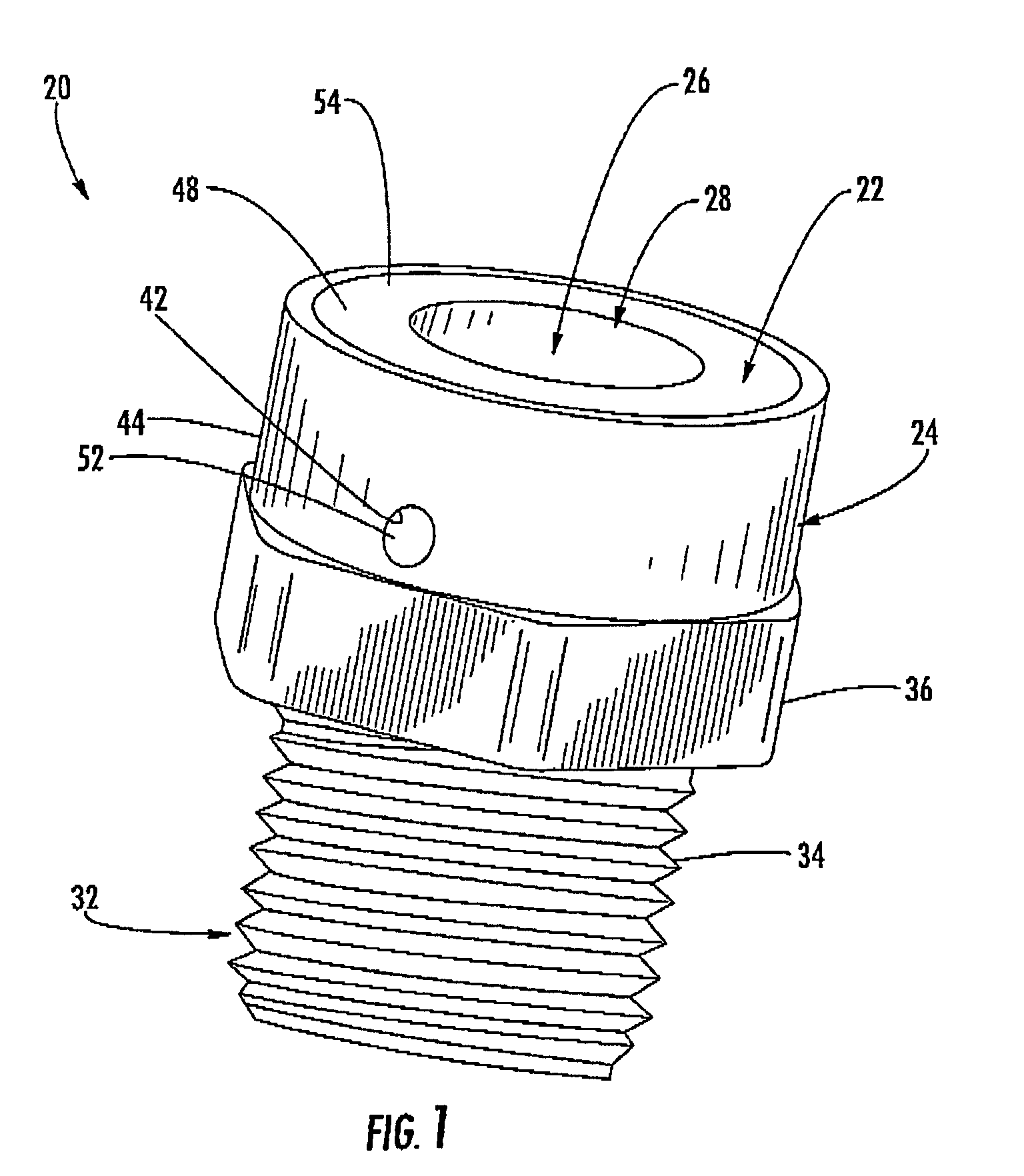
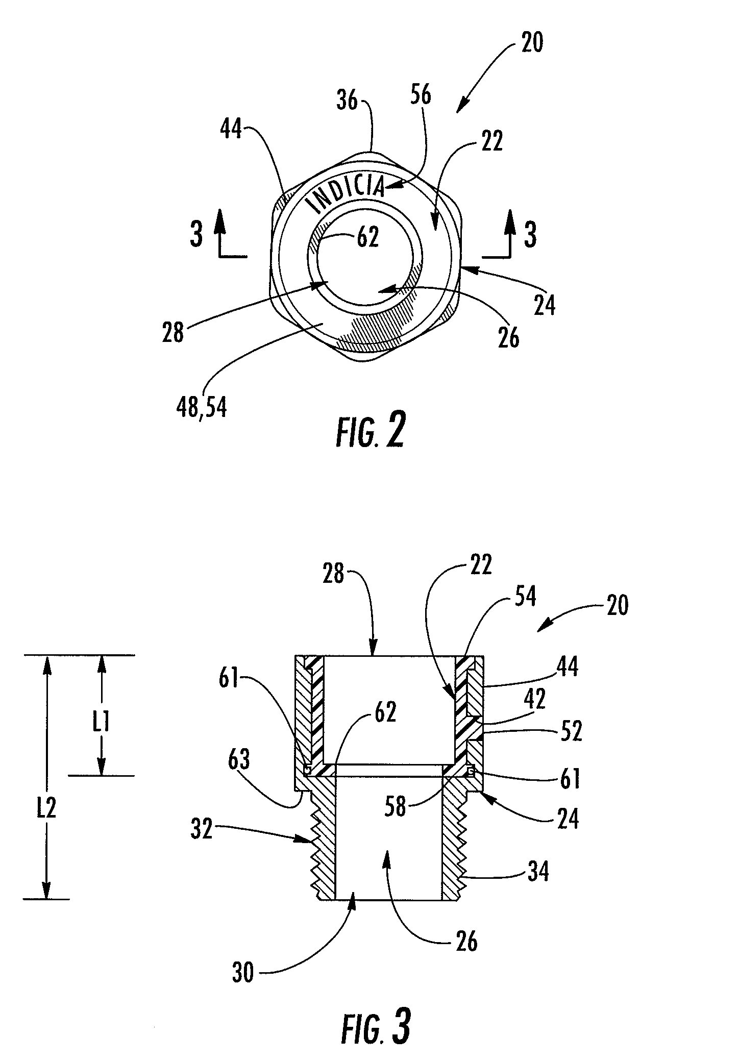
[0035]FIG. 1-3 illustrate a composite fitting 20 that is suitable for connecting between pieces of plumbing such as, but not limited to, polymeric and metallic pipes, in accordance with an exemplary embodiment of the present invention. Although the composite fitting 20 is often described herein in the context of connecting between polymeric and metallic pipes, the composite fitting 20 has other uses that are not limited to connecting between polymeric and metallic pipes. As one example, rather than being conne...


PUM

PropertyMeasurementUnit
angleaaaaaaaaaa
90° angleaaaaaaaaaa
angleaaaaaaaaaa

Abstract

A pipe fitting includes a polymeric body molded into and fixedly connected to a metallic body, so that the metallic body extends around the polymeric body. The polymeric body extends around and is contiguous with a passageway of the pipe fitting, and at least partially defines a first opening of the passageway that is for being mated to a polymeric pipe. The metallic body extends around and is contiguous with the passageway, and at least partially defines a second opening of the passageway that is for being mated to a metallic pipe.

Description

CROSS-REFERENCE TO RELATED APPLICATION[0001]The present application claims the benefit of U.S. Provisional Application 60 / 496,808, which was filed Aug. 21, 2003, and is incorporated herein by reference.BACKGROUND OF THE INVENTION[0002]One aspect of the present invention relates to a pipe fitting for connecting between dissimilar pipes, or the like, and, more particularly, for connecting between metallic and polymeric pipes, or the like.[0003]It is common for substances to flow between metallic and polymeric pipes that are connected by a pipe fitting. As a more specific example, water is often supplied from an upstream metallic pipe to a downstream polymeric pipe that is the inlet of a plumbing fixture or appliance, such as a faucet or the like. It is critical for this type of pipe fitting to remain watertight, often for very many years. Nonetheless, it is common for some of these pipe fittings to occasionally fail, since they are typically exposed to many cycles of stress caused by ...

Claims


Application Information

Patent Timeline
Patent Type & Authority Patents(United States)
IPC IPC(8): F16L47/02F16L47/06F16L47/16B21K1/16F16L13/007F16L47/24
CPCB21K1/16F16L47/24Y10T29/4943
Inventor LEWIS, ERIC WAYNEPARKER, JULIE STARNES
Owner CHARLOTTE PIPE & FOUNDRY
Learn More