
Quill shaft extractor for the 700 series aircraft

Active Publication Date: 2009-04-21
AGUILAR DAVID B
View PDF8 Cites 57 Cited by
  • Summary
  • Abstract
  • Description
  • Claims
  • Application Information

AI Technical Summary

Benefits of technology

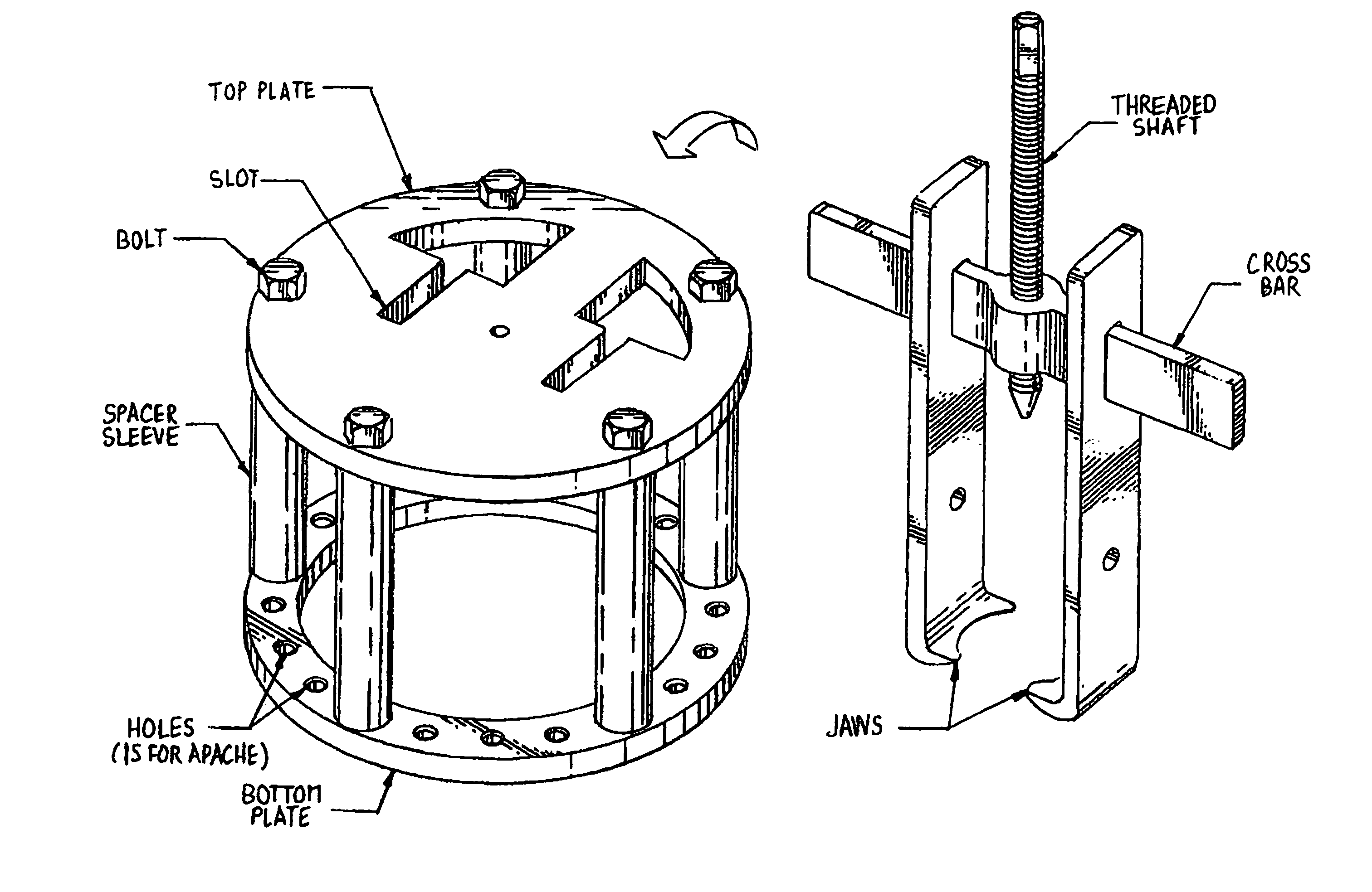
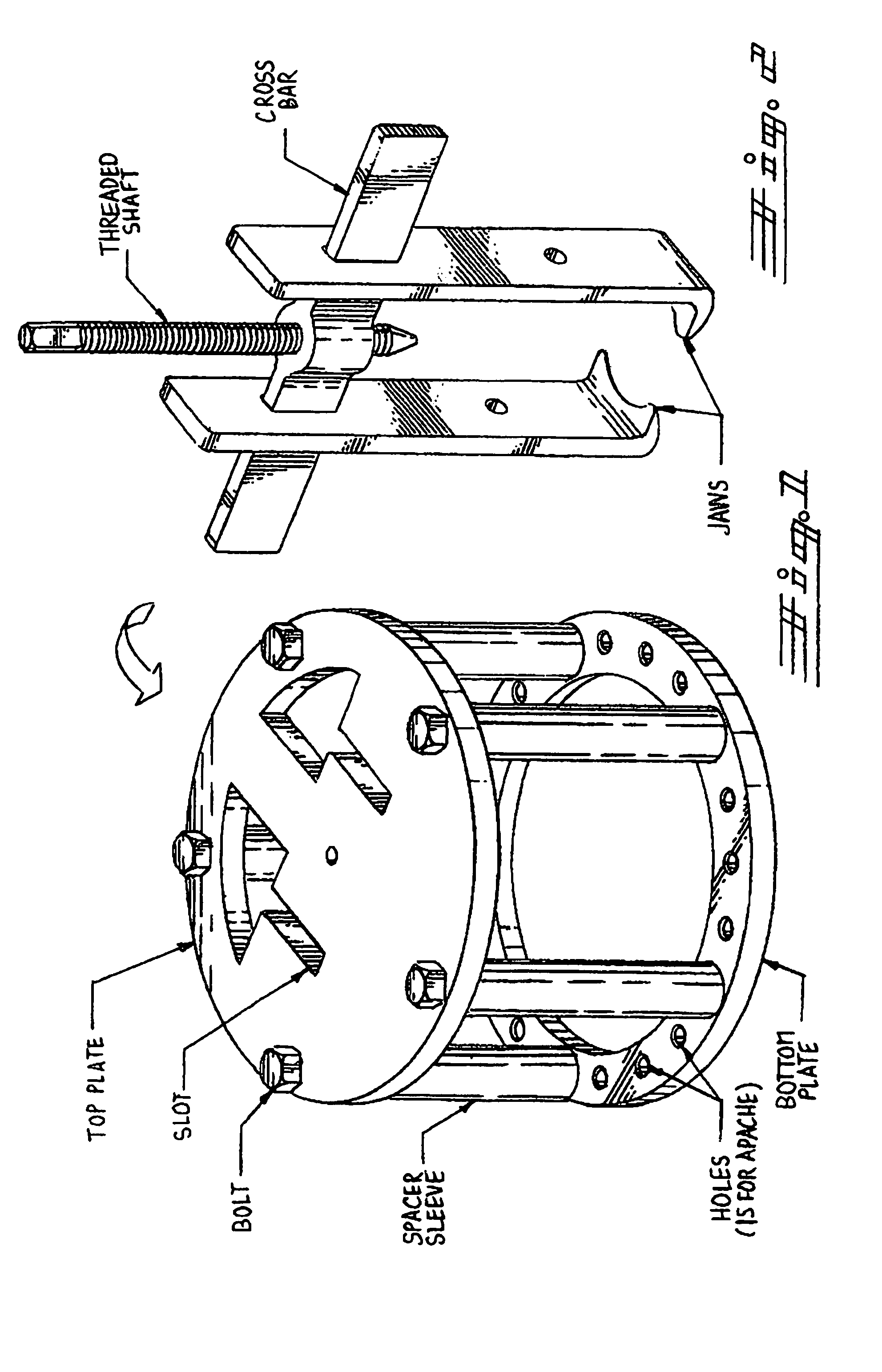
[0021]The extractor incorporates an alignment housing coupled with an extractor unit. The alignment unit consists of a top plate with alignment holes for the two pullers as well as a bottom plate that has mounting holes unique to the T-700 turboshaft engine with both plates held together by spacer sleeves. The extractor unit incorporates a

Problems solved by technology

There are two main problems with this method:1. Safety Hazard;(a) The engine gear box is located about 8 to 9 feet above the ground level.
Upon removing the engine gear nose box from the engine we have realized that many quill shafts have been jammed in place.
To remove the shaft from the engines is the issue.

Method used


Image

  • Quill shaft extractor for the 700 series aircraft
  • Quill shaft extractor for the 700 series aircraft

Examples


Embodiment Construction

[0026]The present invention relates to an extractor tool used to remove the quill shaft unique to the General Electric T-700 series turboshaft engine when used as the powerplant for the AH-64A & D model Apache Helicopters.

[0027]The extractor incorporates an alignment housing coupled with an extractor unit. The alignment unit consists of a top plate with alignment holes for the two pullers as well as a bottom plate that has mounting holes unique to the T-700 turboshaft engine with both plates held together by spacer sleeves. The extractor unit incorporates a threaded shaft with a machined point that is threaded through a crossbar. The crossbar holds two individual jaws that slide onto the crossbar and are used to grasp and remove the quill shaft when the quill shaft is mounted in the T-700 Series engine and installed for use as the primary powerplant in the AH-64A & D model Apache Helicopters.

[0028]The primary object of the present invention is to provide an extractor tool for removi...


PUM

PropertyMeasurementUnit
Angleaaaaaaaaaa

Abstract

An extractor tool used to remove the quill shaft unique to the General Electric T-700 series turboshaft engine when used as the powerplant for the AH-64A & D model Apache Helicopters. The extractor incorporates an alignment housing coupled with an extractor unit. The alignment unit consists of a top plate with alignment holes for the 2 pullers as well as a bottom plate that has mounting holes unique to the T-700 turboshaft engine with both plates held together by spacer sleeves. The extractor unit incorporates a threaded shaft with a machined point that is threaded through a crossbar. The crossbar holds 2 individual jaws that slide onto the crossbar and are used to grasp and remove the quill shaft when the quill shaft is mounted in the T-700 Series engine and installed for use as the primary powerplant in the AH-64A & D model Apache Helicopters.

Description

RELATED APPLICATIONS[0001]This application claims priority from a U.S. Provisional Patent Application PTO 60 / 779,388, filed on Mar. 3, 2006.FIELD OF THE INVENTION[0002]The Quill Shaft Extractor for the 700 Series Aircraft is designed to facilitate the safe and efficient extraction of a quill shaft from an Apache Aircraft.BACKGROUND OF THE INVENTION[0003]The method currently in use to perform the task of removing a Quill Shaft from the engine of an Apache Aircraft requires more then one mechanic and is considered a job that require alertness and caution. The Quill Shaft Extractor for the 700 Series Aircraft is relatively simple to manufacture and use. The current removal method of extracting the Quill Shaft requires two to three personnel in order to remove the Quill Shaft. It has also taken as long as one to five hours to remove the shaft depending how dry the O-rings on the shaft are. TM-1-11520-238-23 par 6.36 Item K states:[0004]1. Pull shaft (23) straight out to remove from engi...

Claims


Application Information

Patent Timeline
IPC IPC(8): B23P19/04
CPCB25B27/023Y10T29/53843Y10T29/53861Y10T29/53943Y10T29/53909
Inventor AGUILAR, DAVID B
Owner AGUILAR DAVID B
Learn More