
Method for determining the temperature of a surface coating

a surface coating and temperature technology, applied in the direction of instruments, heat measurement, measurement devices, etc., can solve the problems of general failure of thermoelements and cases destroyed, and achieve the effect of simple, reliable and accurate determination, and reduced number of components

Inactive Publication Date: 2009-04-14
SIEMENS AG
View PDF14 Cites 2 Cited by
  • Summary
  • Abstract
  • Description
  • Claims
  • Application Information

AI Technical Summary

Benefits of technology

[0006]The object of the present invention is therefore to provide a method and a device for carrying out the method, by means of which the temperature of the surface coating of rotating blades and / or guide vanes can be determined in as simple, reliable and accurate a manner as possible.
[0017]It is advantageous here for the electromagnetic waves to be emitted by means of the at least one antenna in a directed and / or focused manner. This ensures a targeted temperature measurement. In addition, a spatial resolution of the temperature measurement on the blades can be enabled if the antenna is also fashioned such that translations and / or rotations of the antenna are possible.
[0019]The non-positive-displacement machine is advantageously a gas turbine. It is precisely in the field of heavy machinery that the device according to the invention can achieve a simple, reliable and accurate determination of the temperature of the surface coating of the gas turbine blades, whereby a more effective operation can be ensured and in particular costly downtimes due to maintenance and repair measures because of destroyed surface coatings and blades can be further reduced. For example, an increase in the availability of a power supply equipped with a gas turbine can be achieved in this manner. The device according to the invention can, in addition, be configured such that the impact on the gas flow in the duct of the non-positive-displacement machine is largely minimized.

Problems solved by technology

Due to the high temperatures in the gas flow of the non-positive-displacement machine, the thermoelements generally fail after a few hours of operating time and are in most cases destroyed.

Method used


Image

  • Method for determining the temperature of a surface coating
  • Method for determining the temperature of a surface coating
  • Method for determining the temperature of a surface coating

Examples


Embodiment Construction

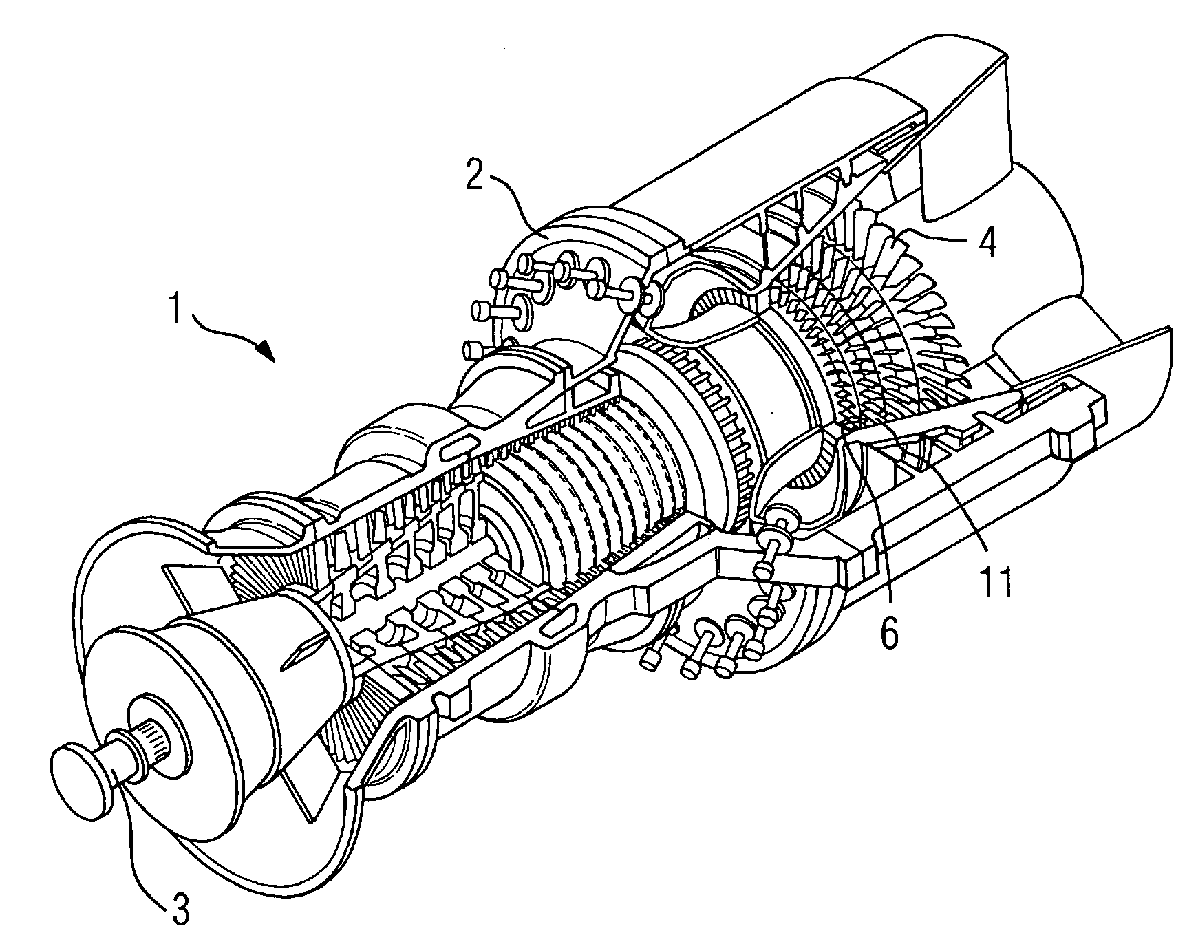
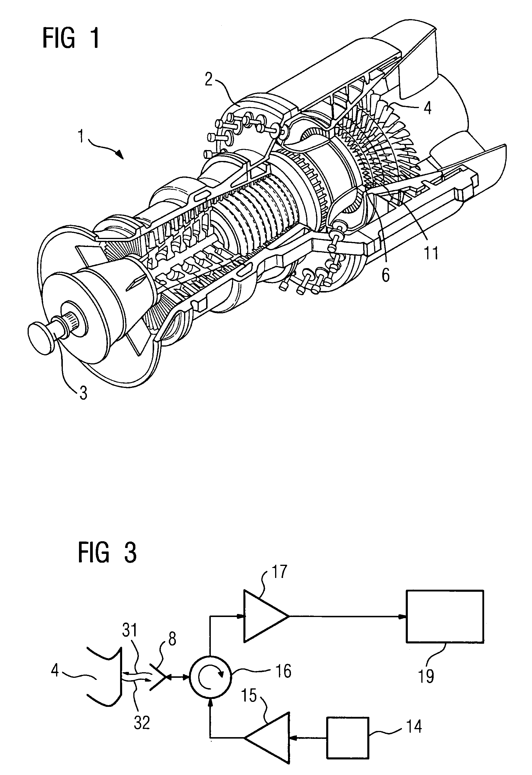
[0029]FIG. 1 shows a prior art gas turbine 1 which is designed for a high gas inlet temperature of around 1200° C. The gas turbine 1 has rotating blades 4 arranged on a rotor shaft 3 rotationally mounted in a housing 2. Provision is also made for guide vanes 11 connected in a rotationally fixed manner to the housing 2 (FIG. 4, FIG. 5). The rotating blades 4 and the guide vanes 11 are in particular respectively furnished with a surface coating 12, 13 in order to withstand the physical loadings in the duct 6 of the gas turbine 1. The coating is, for example “yttrium-stabilized zirconium oxide”.

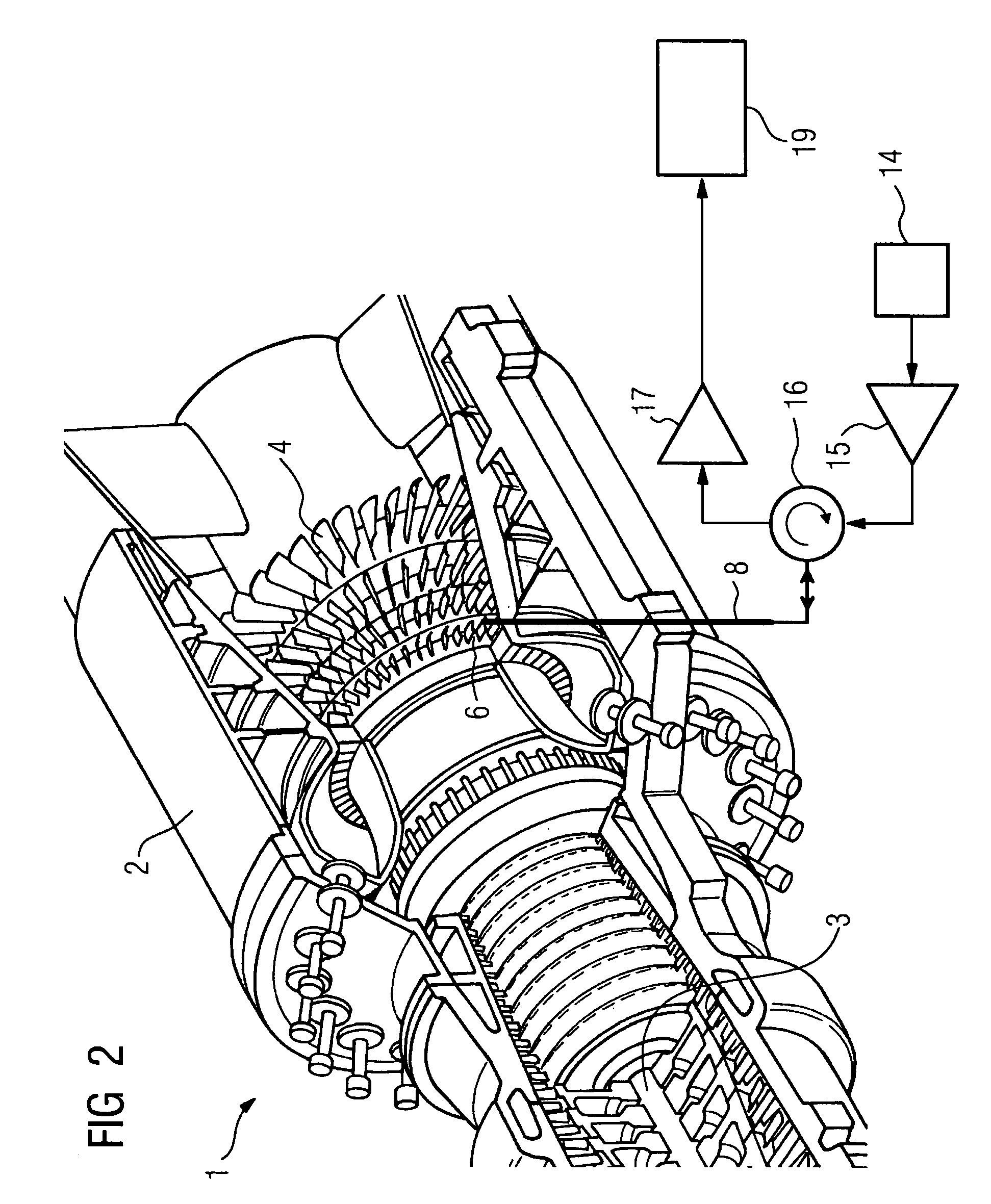
[0030]As shown in FIG. 2, the turbine 1 is equipped with a device according to the invention which has an antenna 8, in particular an antenna fashioned for millimeter waves, which antenna extends into the duct 6 of the gas turbine 1. The antenna 8, which is provided in particular for electromagnetic waves with frequencies from 10 GHz to 130 GHz, is arranged in the area of the rotating blades 4 t...


PUM

PropertyMeasurementUnit
frequencyaaaaaaaaaa
temperatureaaaaaaaaaa
inlet temperatureaaaaaaaaaa

Abstract

The invention relates to a method for determining the temperature of a surface coating of rotating blades mounted in a non-positive-displacement machine with a rotor shaft rotationally mounted in a housing, during which electromagnetic waves are emitted in a duct in an area of the rotating blades by at least one means for generating electromagnetic waves. The electromagnetic waves are reflected, at least in part, by at least one rotating blade. The reflected portions of the electromagnetic waves are received by at least one receiving means and the temperature of the surface coating of the rotating blades is determined from a distribution of intensity of the received electromagnetic waves. The invention also relates to a method for determining the temperature of a surface coating of guide vanes mounted in a rotationally fixed manner in a non-positive-displacement machine with a housing, and to a device for carrying out the method.

Description

CROSS REFERENCE TO RELATED APPLICATIONS[0001]This application is the US National Stage of International Application No. PCT / EP2005 / 055141, filed Oct. 11, 2005 and claims the benefit thereof. The International Application claims the benefits of German application No. 10 2004 050 906.9 filed Oct. 19, 2004, both of the applications are incorporated by reference herein in their entirety.FIELD OF INVENTION[0002]The present invention relates to a method for determining the temperature of a surface coating of rotating blades arranged in a non-positive-displacement machine on a rotor shaft rotationally mounted in a housing. The invention also relates to a method for determining the temperature of a surface coating of guide vanes arranged in a rotationally fixed manner in a non-positive-displacement machine with a housing, and to a device for carrying out the method.BACKGROUND OF THE INVENTION[0003]Non-positive-displacement machines such as, for example, steam or gas turbines, are employed a...

Claims


Application Information

Patent Timeline
Patent Type & Authority Patents(United States)
IPC IPC(8): G01K11/00
CPCG01K11/006
Inventor BOSSELMANN, THOMASHUBER, KLAUSPEREZ, FRANCISCO JAVIER SEVILLAWILLSCH, MICHAEL
Owner SIEMENS AG
Learn More