Glass cassette for scanning imaging plates

a scanning imaging and cassette technology, applied in the field of xray cassettes and computed radiography, can solve the problems of limited reusability, increased wear and tear of the plate, and degradation of the quality

Inactive Publication Date: 2009-03-24
ICRCO
View PDF11 Cites 6 Cited by
  • Summary
  • Abstract
  • Description
  • Claims
  • Application Information

AI Technical Summary

Benefits of technology

[0013]This present invention provides an enclosure adapted for supporting at least one imaging plate for use in a computed radiography or similar device. The enclosure comprises a first flat side having an exposure window and a second flat side generally opposite the first side. The enclosure also includes at least one side section interco

Problems solved by technology

Over time the flexing and contact with the rollers causes a deleterious effect on the plate resulting in limited reusability.
Additional wear and tear on the plate is caused by the removal and replacement of the plate in a cassette that protects the plate from ambient energy (light) sources during transportation.
In addition to causing degradation of the quality of the plate the pinch rollers can slip causing line artifacts and blurring of the image being generated.
The issue of scanning imaging plates in CR and related scanning devices is surprisingly complex.
A critical difference between scanning film and CR plates is that the CR plate is removed, read and replaced over and over again, resulting in stresses to and ultimately, potential failure of the CR plate.
Some of these methods may extend or reduce the life of the CR plate through the respective increase or decrease in handling and stress to the plates.
Current CR plates have design limitations and constraints that include coatings and materials that may be able to withstand limited deformation through bending and surface contact of pinch rollers.
Often times, these designs have cycle or use limitations for the CR plate due to the manual handling of the plate and related stresses and or damage to the plate due to the scanning process.
Another limitations to the precision of the CR scan process is the mechanism used to drive the CR plate in front of the scan head.
If the process depends on pinch rollers, any slippage can cause line artifacts or simply blurring of the image.
This error is similar to that found in facsimile machines that rely on pinch rollers to drive the paper past the read head.
This technology, however, has had many problems with the reader, not the least issue is that the plates are made of delicate crystals of a glass like phosphor material.
These needles are prone to breaking if the cassette is dropped.

Method used


Image

  • Glass cassette for scanning imaging plates
  • Glass cassette for scanning imaging plates
  • Glass cassette for scanning imaging plates

Examples


Embodiment Construction

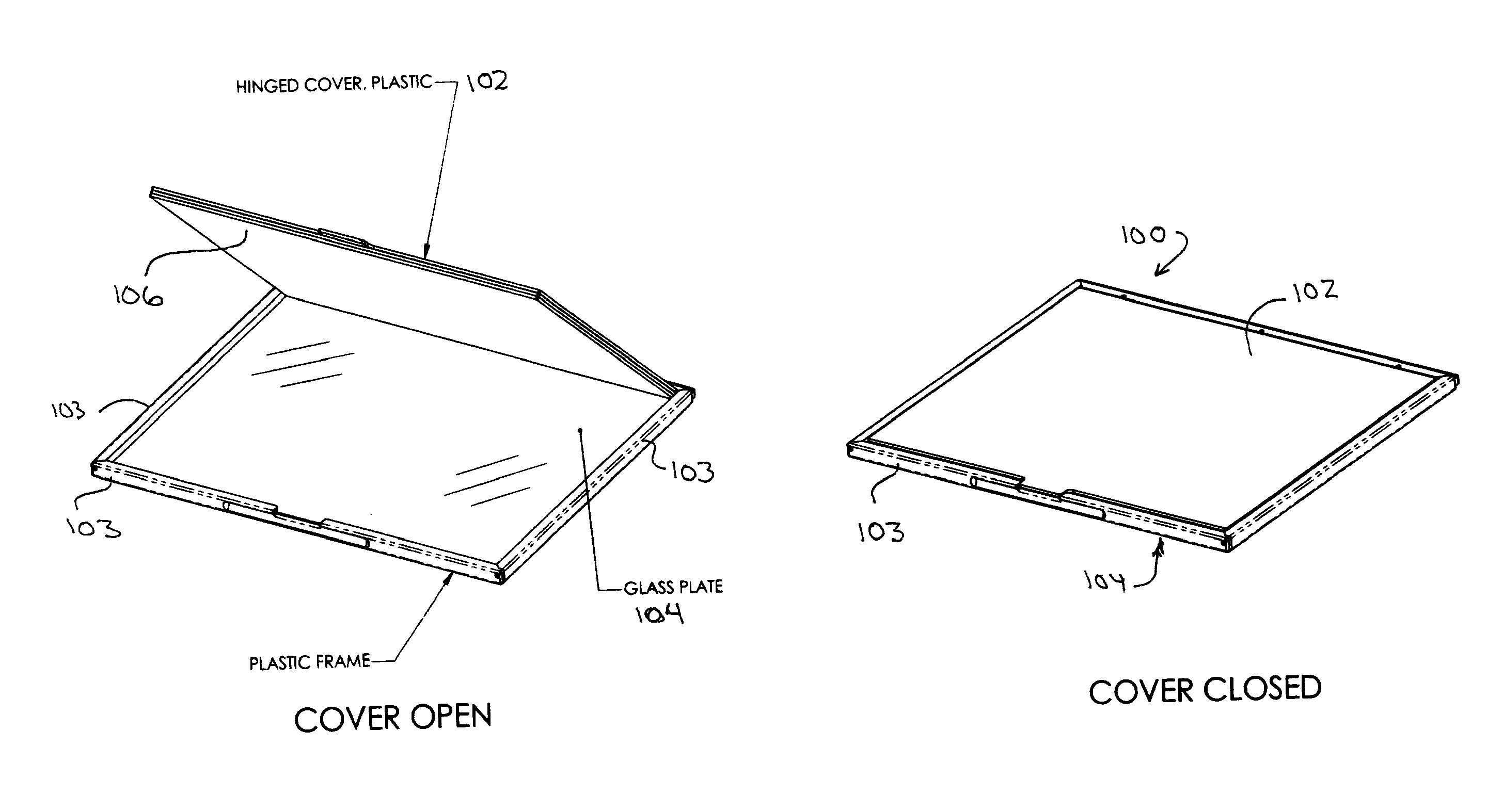
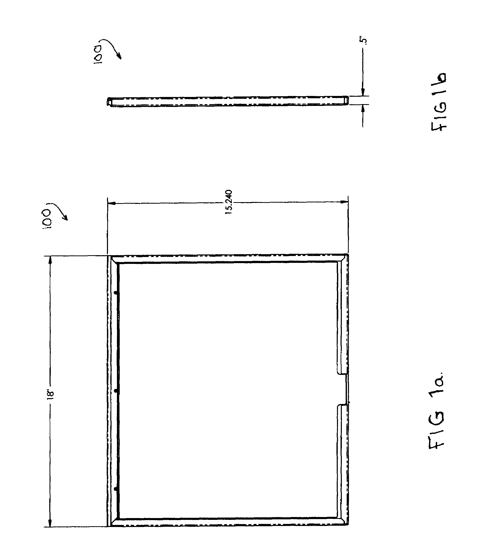
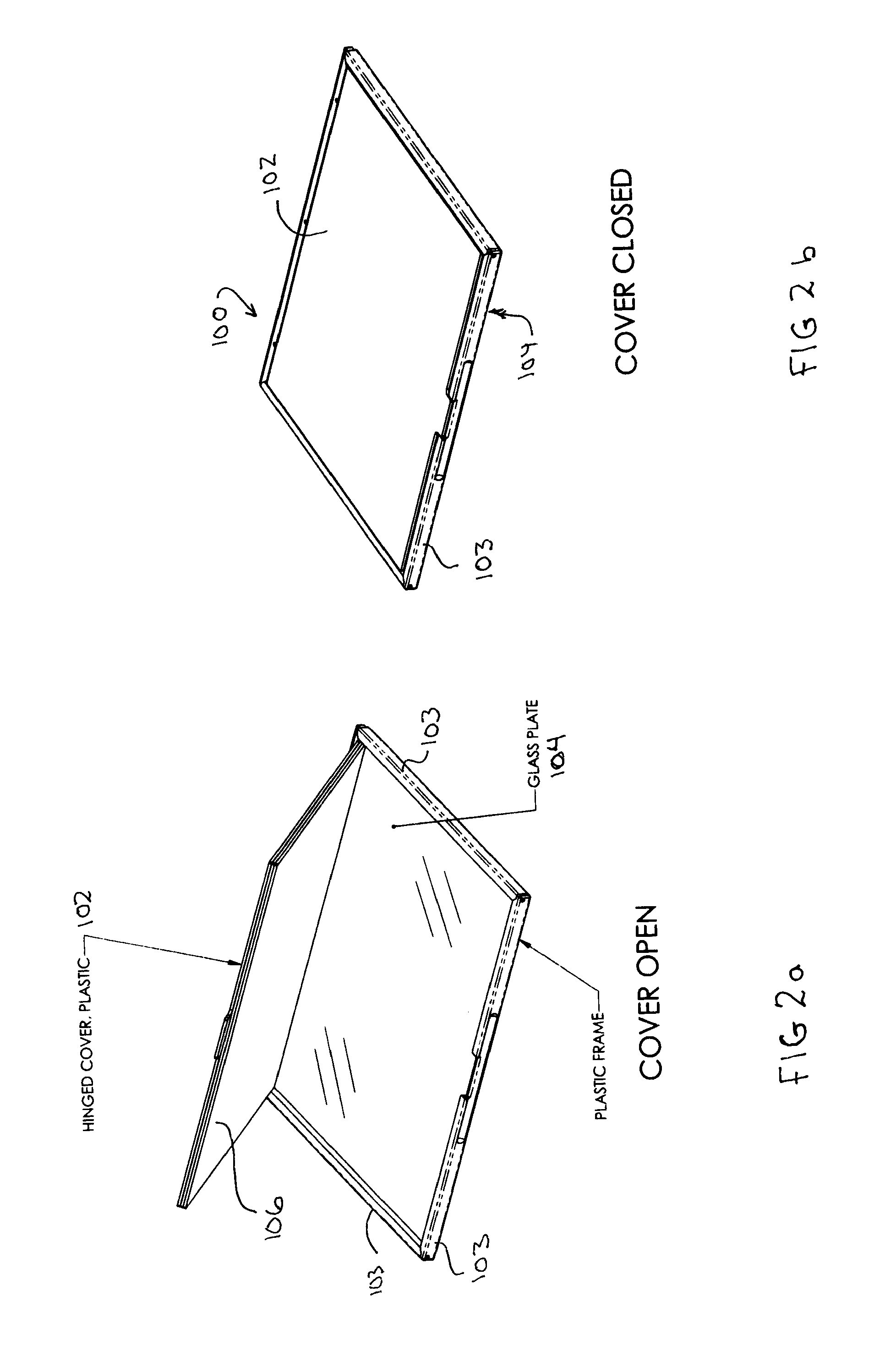
[0022]Existing CR cassette designs and methods include a CR scanning cycle of a rigid, flat cassette and imaging plate assembly without requiring the removal of the imaging plate from the cassette. In this design, the CR cassette is opened during the scan process to allow access to the imaging plate. This generally creates a precise, flat read cycle of the imaging plate limited only by the precision of the drive mechanism employed to open and move the cassette past the scan head. In this preferred scan process, nothing touches the surface of the phosphor plate and the imaging plate is kept flat over the area being scanned. As the cassette passes the scanning head of the CR, at least one side of the cassette is opened, exposing the imaging plate. This creates a scan cycle that reduces wear on the phosphor material of the imaging means, greatly enhancing the lifetime of the imaging means and improves the quality of the read cycle. In addition, the scan time is much reduced because the...


PUM


Abstract

The invention provides a cassette enclosure having an energy translucent portion for supporting an imaging plate. The cassette is adapted for use with a computed radiography device wherein an image set forth on the imaging plate can be scanned without removing the plate from the cassette.

Description

CROSS-REFERENCE TO RELATED APPLICATION[0001]The present application claims priority from U.S. Provisional Patent Application Ser. No. 60 / 779,047, entitled “Glass Cassette For Scanning imaging Plates”, filed on Mar. 3, 2006, which is hereby incorporated by reference in its entirety into this disclosure. The present application is also a Continuation-In-Part of co-pending application Ser. No. 10 / 714,087, filed on Nov. 13, 2003 by applicant Stephen Neushul entitled, “Computed Radiography X-Ray Cassette With Rigid Embedded CR Plate,” which is a divisional of Ser. No. 09 / 747,616 filed Dec. 20, 2000 Issued U.S. Pat. No. 6,532,092, which is a Continuation of Ser. No. 09 / 450,031 filed Nov. 24, 1999 Issued U.S. Pat. No. 6,188,501.BACKGROUND OF THE INVENTION[0002]1. Field of the Invention[0003]The present invention relates to x-ray cassettes and computed radiography and related imaging plates. More specifically, the invention relates to a novel cassette devices for supporting an imaging plate...

Claims


Application Information

Patent Timeline
IPC IPC(8): H05B33/00
CPCG02B27/023H04N2201/0412H04N2201/0422
Inventor NEUSHUL, STEPHEN
Owner ICRCO
Why Eureka
Try Eureka