Adjustable bi-fold tray table

a tray table and folding technology, applied in the direction of aircraft crew accommodation, seating arrangements, transportation and packaging, etc., can solve the problems of insufficient length of fully withdrawn and positioned tray tables, inability to move in the lateral or “cross-craft” direction, and unstable tray tables. achieve the effect of preventing twisting of tray tables and increasing surface area

Active Publication Date: 2009-03-24
BE AEROSPACE INCORPORATED
View PDF15 Cites 81 Cited by
  • Summary
  • Abstract
  • Description
  • Claims
  • Application Information

AI Technical Summary

Benefits of technology

[0014]The adjustment assembly includes at least one guide attached to the first tray table portion along which a guide bracket slides to provide fore and aft movement of the tray table relative to the fixed tray table support arm. The support arm is “fixed” in the sense that it does not move once positioned in the “in use” position. The guide bracket is further slidably received within an elongated opening defined by the tray table support arm, which allows the bracket, and in turn the tray table, to move laterally across the seat with respect to the “fixed” tray table support arm. Thus, the adjustment assembly provides selective fore, aft and lateral movement of the tray table for maximum adjustability.
[0016]The adjustment assembly includes a pair of guide rods mounted to the bottom surface of the first tray portion. A guide bracket slidingly receives the rods through openings defined in the guide bracket. The pair of rods allow the tray table to slide fore and aft relative to the fixed tray table arm while preventing twisting of the tray table. The guide bracket is slidably received within a lateral, elongate opening defined in the fixed tray table support arm. The opening preferably ranges in length from about 1 to about 12 inches, more preferably around 6 inches in length. This provides for about 1 to about 12 inches of travel for the tray table, preferably about 6 inches of travel. By providing a tray table that can unfold to increase the surface area, and providing lateral movement of the tray table, the tray table is able to bridge the gap between armrests of the seat, thus supporting the tray table at both ends. The tray table is supported at the first end by the tray table support arm through the adjustment assembly, and at the second end by the seat armrest.

Problems solved by technology

Once in the working position, the tray table is not capable of being moved in the lateral or “cross-craft” direction and remains laterally fixed between the hinges.
The packaging restraints of the end-bay limit the dimensions of the tray table, thus a fully withdrawn and positioned tray table has a length insufficient to bridge the gap between the armrests of a large seat, such as a first class seat.
Since the tray table is only supported at its hinge end, the tray table is unstable and can suffer from an undesirable “diving board” effect.

Method used


Image

  • Adjustable bi-fold tray table
  • Adjustable bi-fold tray table
  • Adjustable bi-fold tray table

Examples


Embodiment Construction

[0025]The present invention will now be described more fully hereinafter with reference to the accompanying drawings in which exemplary embodiments of the invention are shown. However, the invention may be embodied in many different forms and should not be construed as limited to the representative embodiments set forth herein. The exemplary embodiments are provided so that this disclosure will be both thorough and complete, and will fully convey the scope of the invention and enable one of ordinary skill in the art to make, use and practice the invention. Like reference numbers refer to like elements throughout the various drawings.

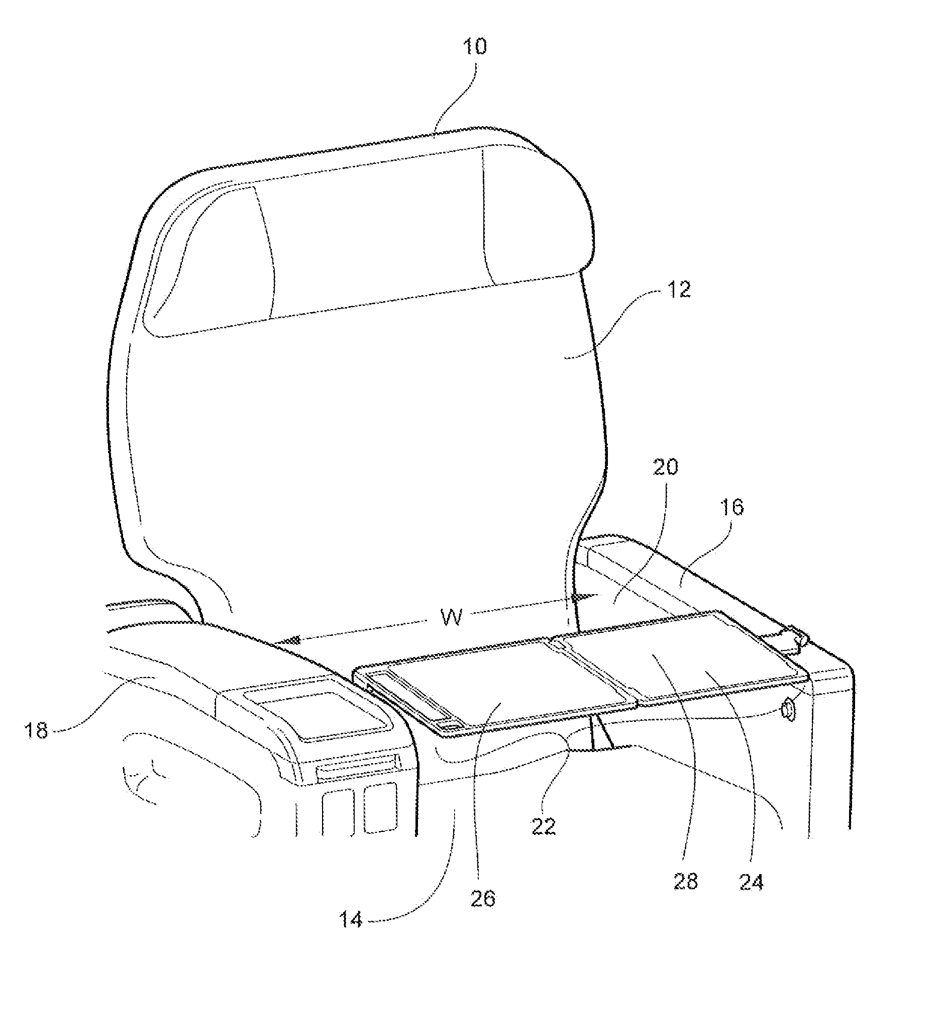
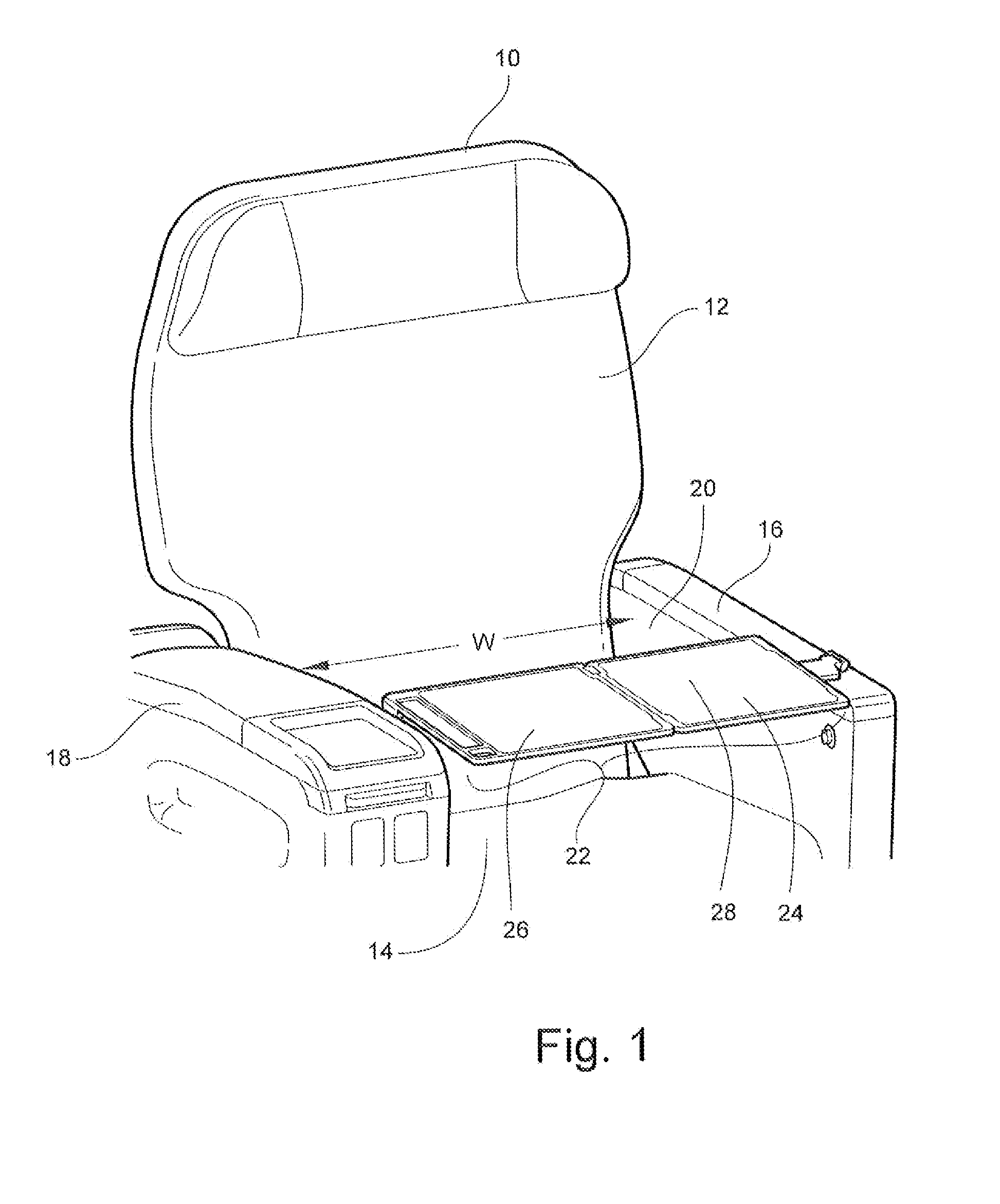
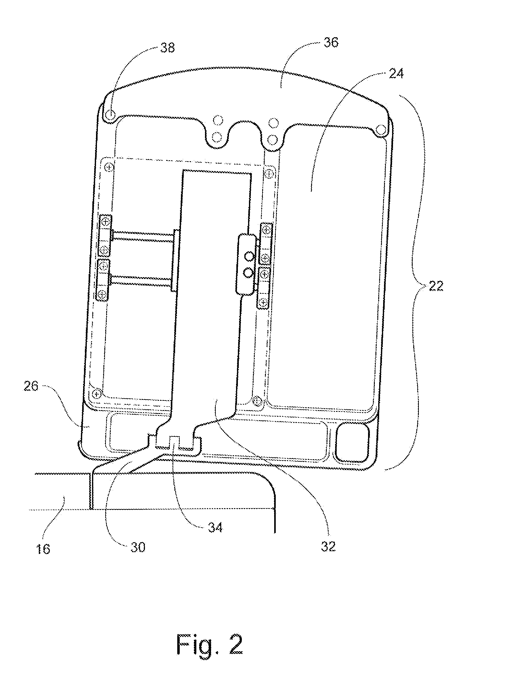
[0026]The present invention provides a tray table for a vehicle passenger seat that is adjustable in the fore / aft and lateral directions to provide maximum tray table adjustability for the seat occupant. The tray table is further laterally extendable to bridge the gap, when unfolded, between armrests of the passenger seat so that the tray table is suppor...


PUM


Abstract

An adjustable tray table assembly for a vehicle seat including a bi-fold tray table, an adjustment assembly for adjusting the tray table in the fore / aft and lateral directions, a support arm for supporting the tray table and slidably receiving the adjustment assembly, and an attachment arm interconnected with the support arm for attaching the tray table assembly to the vehicle seat. The adjustment assembly includes a guide bracket that slides both within an elongated opening of the support arm and along at least one guide attached to the tray table to provide the adjustability.

Description

TECHNICAL FIELD AND BACKGROUND OF THE INVENTION[0001]1. Field of the Invention[0002]The present invention relates generally to a passenger vehicle tray table, and more specifically, to an adjustable bi-fold tray table for a passenger seat that is selectively movable in the fore, aft and lateral directions for maximum adjustability.[0003]2. Description of the Related Art[0004]Passengers seats, such as those found on an aircraft, typically include a seat frame securely mounted to the vehicle floor, a passenger supporting portion including a seat back and a seat bottom mounted to the frame, and a pair of armrests positioned about the sides of the seat bottom. While several functions of the armrests are to provide passenger comfort and define the living space of the seat, the armrests commonly function as mounting surfaces for seat controls, media controls, headphone jacks, attendant calling controls, as well as defining storage compartments and beverage holders.[0005]Vehicle passenger ...

Claims


Application Information

Patent Timeline
IPC IPC(8): A47B83/02
CPCB60N3/002B64D11/0638B64D11/06
Inventor GAUSS, JASON A.
Owner BE AEROSPACE INCORPORATED
Why Eureka
Try Eureka