
Response time compensation using display element modeling

Active Publication Date: 2009-03-03
ROCKWELL COLLINS INC
View PDF5 Cites 0 Cited by
  • Summary
  • Abstract
  • Description
  • Claims
  • Application Information

AI Technical Summary

Benefits of technology

[0015]An advantage of the invention is an improved display element response time using a minimum amount of memory space.
[0016]The invention provides a method of improving response time of a display element in a display. According to the method, a command input is provided that represents a desired response of the display element. The command input is modified, using a compensation function, to produce a command output to be sent to the display element. The compensation function uses the command input and a modeled luminance of the display element in a present state and at least one previous state to compute the command output. The command output is transmitted to the display element.
[0017]The invention also provides a method of adjusting a luminance command to a display element in a liquid

Problems solved by technology

Unlike displays based upon cathode-ray tube (CRT) technology that has nearly instantaneous pulse-type display characteristics, LCDs provide significantly slower response times. Slow response times can result in visible distortion of dynamic images, particularly when the dynamic portion of the images include rapid movement.
Some newer types of LCDs have significantly slower inherent response times, which make this problem more visible and problematic, even at relatively slow rates of image movement.
The slow response times create visible distortions such as smearing or dimming, and can make moving symbology essentially unusable.
Reducing the number of bits stored for each display element reduces output fidelity.
Reducing

Method used


Image

  • Response time compensation using display element modeling
  • Response time compensation using display element modeling
  • Response time compensation using display element modeling

Examples


Example

DETAILED DESCRIPTION OF THE DRAWINGS

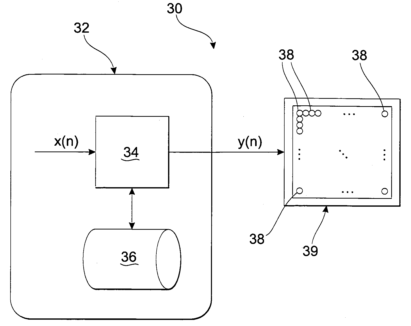
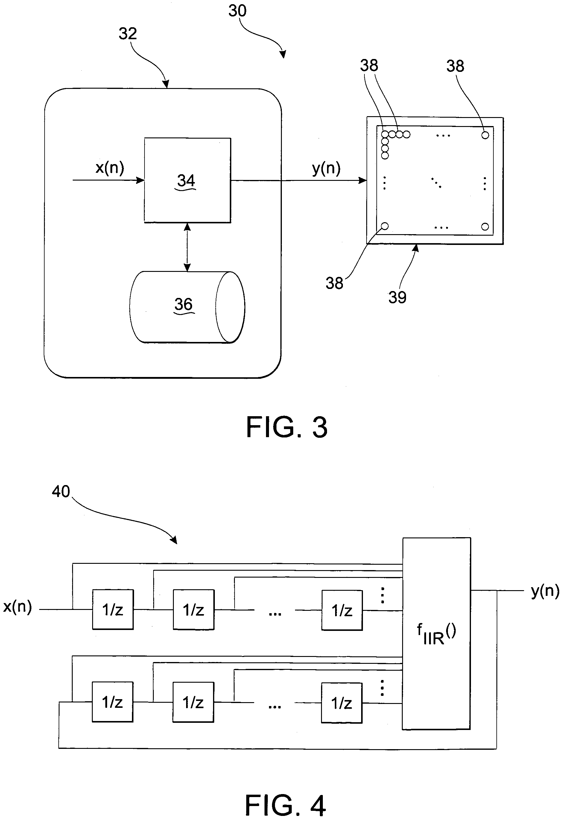
[0026]A system for displaying images on a display is schematically shown in FIG. 3 and generally indicated by reference number 30. System 30 includes a processor 32 having a processing element 34, which may be one of many processing elements within processor. Alternatively, processing element 34 may represent a portion of a single processor. Processing element 34 is operationally connected to a data storage element 36. Data storage element 36 is preferably a random-access memory (RAM) device or another re-writable, fast access memory device. Data storage element 36 is sufficiently large to store previous luminance commands as well as current and previous modeled luminance information for each display element, as will be further described herein. Processing element 34 also receives, as an input, a desired display element luminance command x(n). Processing element 34 transmits a luminance output command y(n) to a display element 38 forming part of a...


PUM


Abstract

A method of improving response time of a display element in a display is disclosed. According to the method, a command input is provided that represents a desired response of the display element. The command input is modified, using a compensation function, to produce a command output to be sent to the display element. The compensation function uses the command input and a modeled luminance of the display element in a present state and at least one previous state to compute the command output. The command output is transmitted to the display element.

Description

FIELD OF THE INVENTION[0001]The invention relates to displays, and more particularly, to the improvement of response times of displays.BACKGROUND OF THE INVENTION[0002]Liquid Crystal Displays (LCDs) have been used for many years to display both static and dynamic images, including video. Unlike displays based upon cathode-ray tube (CRT) technology that has nearly instantaneous pulse-type display characteristics, LCDs provide significantly slower response times. Slow response times can result in visible distortion of dynamic images, particularly when the dynamic portion of the images include rapid movement. Some newer types of LCDs have significantly slower inherent response times, which make this problem more visible and problematic, even at relatively slow rates of image movement. The slow response times create visible distortions such as smearing or dimming, and can make moving symbology essentially unusable.[0003]Significant effort has been made to correct for this slow response ...

Claims


Application Information

Patent Timeline
IPC IPC(8): G09G3/36
CPCG09G3/3611G09G2320/0252G09G2320/0261G09G2340/16
Inventor PERREAULT, WILLIAM G.JOHNSON, RICK J.MOSIER, DONALD E.
Owner ROCKWELL COLLINS INC
Learn More