
Speckle reduction laser and laser display apparatus having the same

a laser and laser display technology, applied in semiconductor lasers, instruments, optical elements, etc., can solve problems such as image quality degradation, and achieve the effect of reducing speckles

Active Publication Date: 2009-02-10
SAMSUNG ELECTRONICS CO LTD
View PDF0 Cites 30 Cited by
  • Summary
  • Abstract
  • Description
  • Claims
  • Application Information

AI Technical Summary

Problems solved by technology

However, when an image is realized using a laser as a light source, the image quality is degraded due to speckles caused by the coherence of the laser light.

Method used


Image

  • Speckle reduction laser and laser display apparatus having the same
  • Speckle reduction laser and laser display apparatus having the same
  • Speckle reduction laser and laser display apparatus having the same

Examples


Embodiment Construction

[0031]A speckle reduction laser and a laser display apparatus according to the present invention will now be described more fully with reference to the accompanying drawings in which exemplary embodiments of the invention are shown. In the drawings, the thicknesses of layers and regions are exaggerated for clarity, and like reference numerals refer to the like elements.

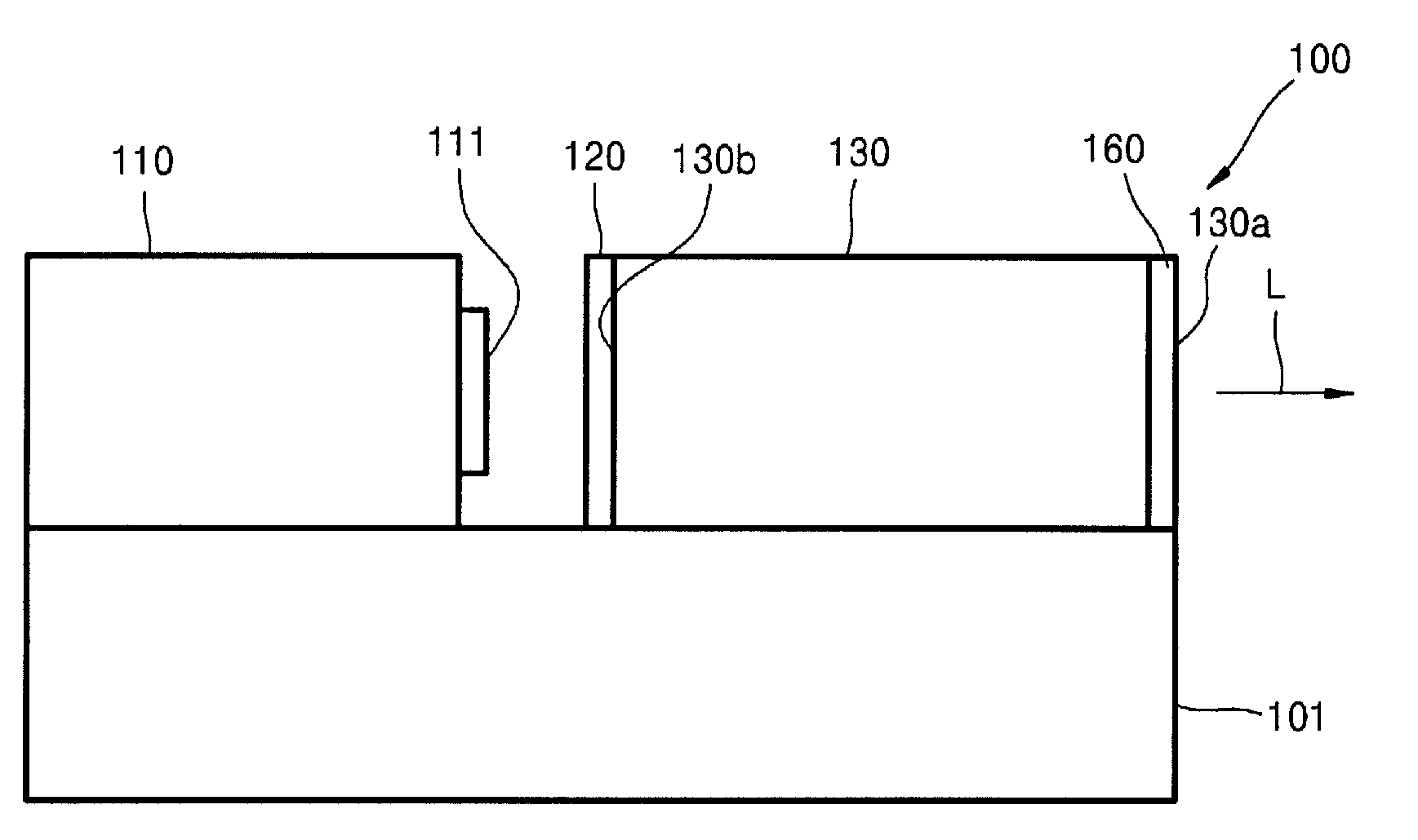
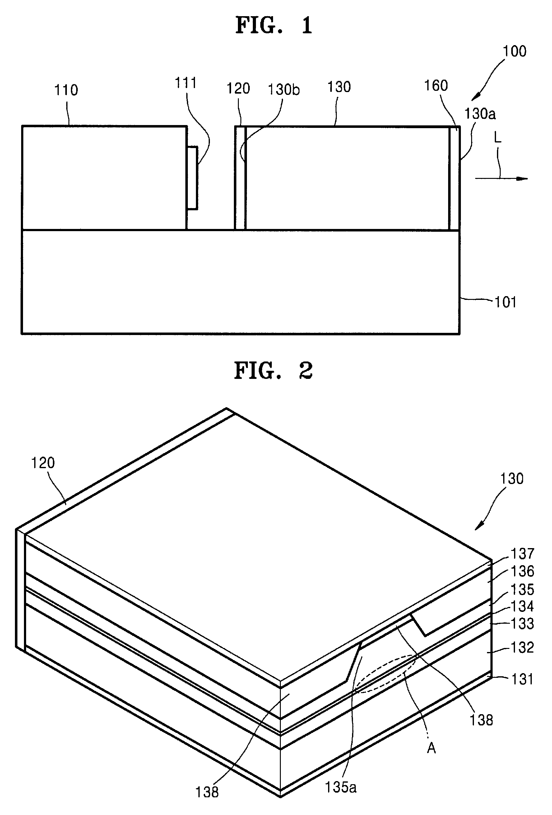
[0032]FIG. 1 is a schematic cross-sectional view illustrating a speckle reduction laser according to an embodiment of the present invention.

[0033]Referring to FIG. 1, the speckle reduction laser according to the present embodiment includes a semiconductor unit 130 that emits laser light and a vibration mirror unit 110 placed on a mount 101. The semiconductor unit 130 according to the present embodiment has a side lighting laser resonance structure in which laser light is emitted from a first side surface 130a. An antireflective member 120 is provided on a second side surface 130b of the semiconductor unit 130 so that ...


PUM


Abstract

A speckle reduction laser and a laser display apparatus having the speckle reduction laser are provided. The speckle reduction laser includes a semiconductor unit that comprises an active layer and emits laser light through a first side surface thereof by resonating light generated from the active layer, and a vibration mirror unit disposed adjacent to a second side surface of the semiconductor unit. The laser further includes a mirror, and the resonance of the laser light is generated between the first side surface of the semiconductor unit and the mirror, and a resonance mode of the laser light is changed according to the vibration of the mirror.

Description

CROSS-REFERENCE TO RELATED PATENT APPLICATION[0001]This application claims priority from Korean Patent Application No. 10-2007-0008585, filed on Jan. 26, 2007, in the Korean Intellectual Property Office, the disclosure of which is incorporated herein in its entirety by reference.BACKGROUND OF THE INVENTION[0002]1. Field of the Invention[0003]Apparatuses consistent with the present invention relate to a speckle reduction laser and a laser display apparatus having the same, and more particularly, to a speckle reduction laser that reduces speckles by changing a resonance mode and a laser display apparatus having the same.[0004]2. Description of the Related Art[0005]With the rapid emergence of multi-media society, the demands for displaying large, high definition images have constantly increased. Also, recent multi-media advancements provide for the realization of an improved natural color in addition to displaying large, high resolution images.[0006]In order to realize an improved natu...

Claims


Application Information

Patent Timeline
Patent Type & Authority Patents(United States)
IPC IPC(8): H01S3/123H01S3/08H01S3/10
CPCG02B27/48H01S5/14H04N9/3129H01S5/028H01S5/1039H01S5/2231H01S3/10H01S5/00
Inventor PARK, YONG-HWAHA, KYOUNG-HOKIM, JUN-OMUN, YONG-KWEUN
Owner SAMSUNG ELECTRONICS CO LTD
Learn More