
Air scoop device

a scoop device and air technology, applied in the direction of roofs, special-purpose vessels, vessel construction, etc., can solve the problems of no means for the use of these devices, and the driving of open-top vehicles or watercraft over long and short distances is not comfortabl

Inactive Publication Date: 2009-01-27
HEARNE BRUCE
View PDF6 Cites 3 Cited by
  • Summary
  • Abstract
  • Description
  • Claims
  • Application Information

AI Technical Summary

Benefits of technology

The air scoop device effectively directs fresh air to the foot-well area, enhancing cooling of the lower waist region during driving by leveraging the airflow dynamics, while being non-obtrusive and cost-effective.

Problems solved by technology

Generally open top vehicles or watercraft driving over long and short distances are not comfortable due to ineffective methods of directing ventilation to the lower body and foot-well areas, thereby cooling the same.
While conventional ventilation devices including air conditioning are suited for their intended usage, none of these devices utilize means that are sized and designed to allow a sufficient airflow at higher speeds to the foot-well area to keep the driver and passengers cool below the waist.

Method used


Image

  • Air scoop device
  • Air scoop device
  • Air scoop device

Examples


Embodiment Construction

[0015]The exemplary embodiments described herein detail for illustrative purposes are subject to many variations in structure and design. It should be emphasized, however, that the present invention is not limited to a particular air scoop device, as shown and described. It is understood that various omissions, substitutions of equivalents are contemplated as circumstances may suggest or render expedient, but is intended to cover the application or implementation without departing from the spirit or scope of the claims of the present invention.

[0016]The terms “first,”“second,” and the like, herein do not denote any order, quantity, or importance, but rather are used to distinguish one element from another, and the terms “a” and “an” herein do not denote a limitation of quantity, but rather denote the presence of at least one of the referenced item.

[0017]The present invention provides an air scoop device that cools the foot-well area of open top vehicles, for example, convertible car...


PUM


Abstract

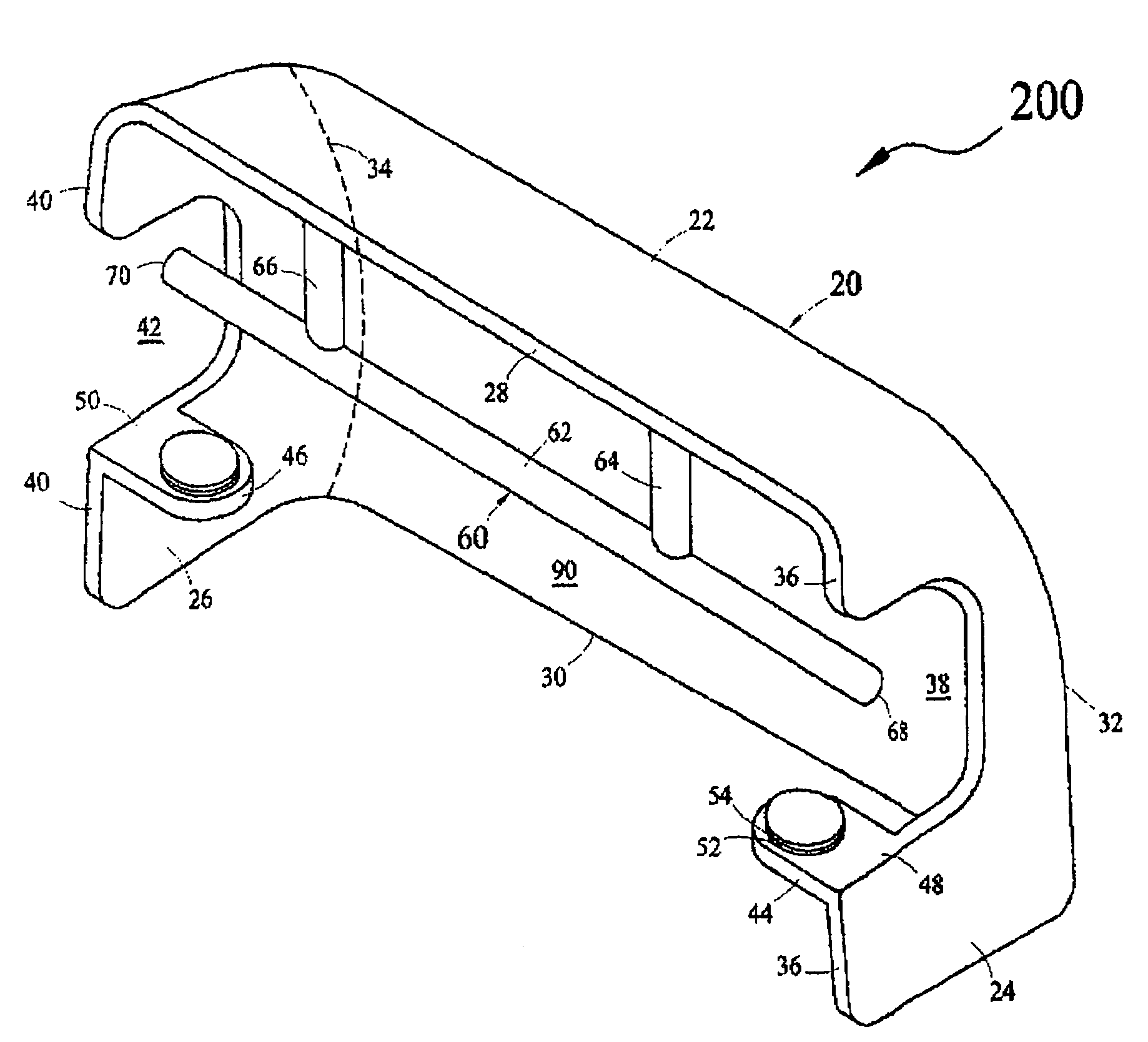
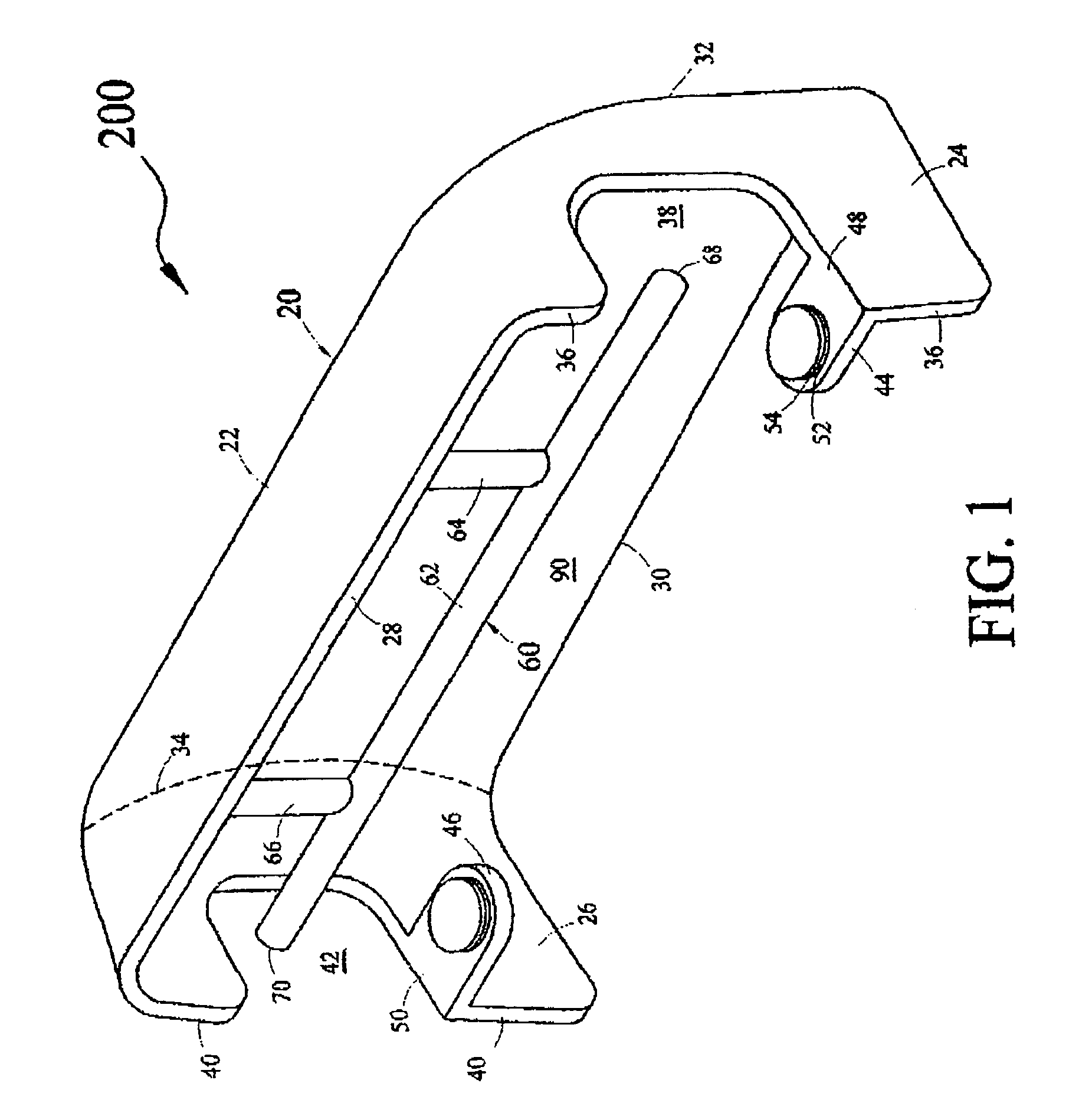
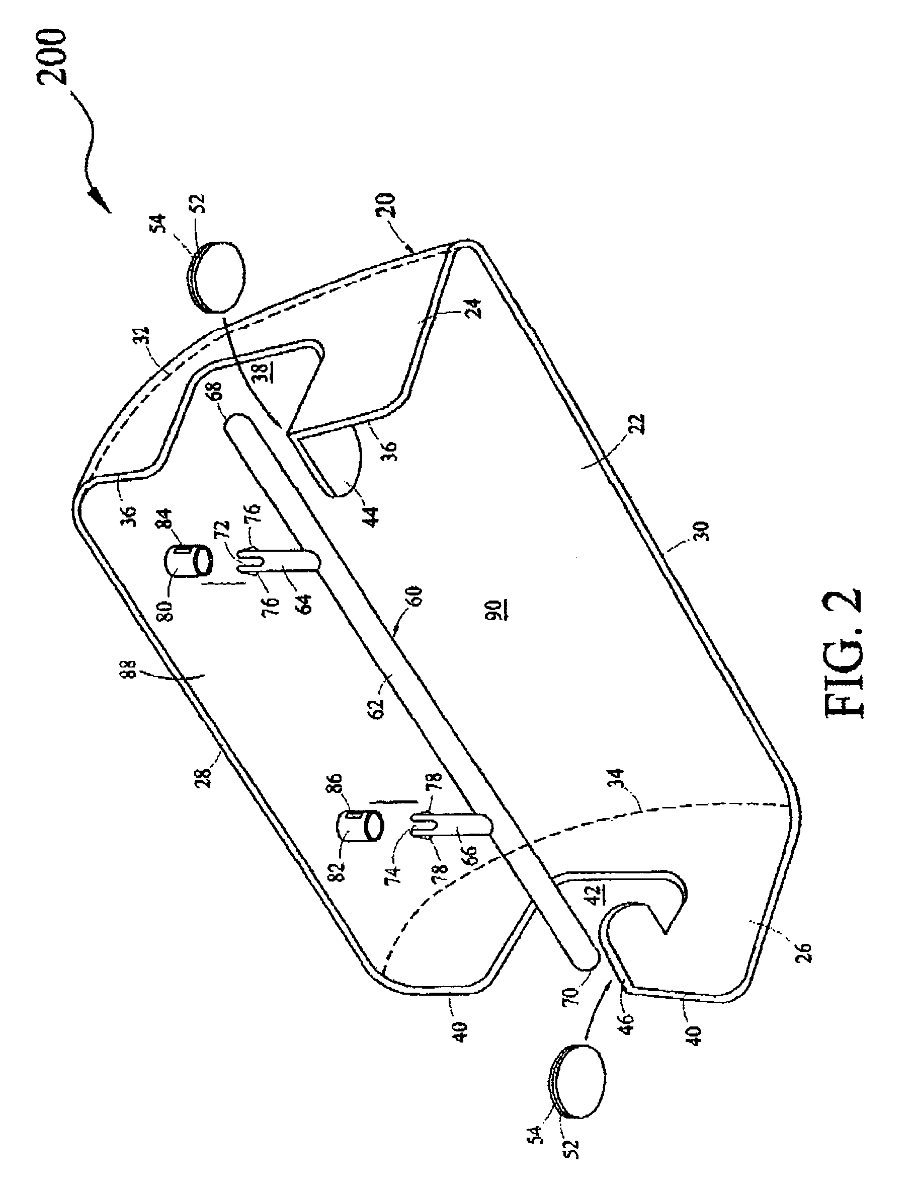
Disclosed is an air scoop device for installation on a windshield header member of an open top vehicle, for example, convertible cars, water boats, water crafts and the like. The air scoop device has a scoop body configuring a hollow interior space capable of receiving air through a first area into the hollow interior space and directing the air out of the hollow interior space through a second area towards a foot-well area of the open top vehicle.

Description

FIELD OF THE INVENTION[0001]The present invention relates to an air scoop device for cooling foot-well area of open top vehicles, for example, convertible cars, water boats, water crafts, and the like, in driving state.BACKGROUND OF THE INVENTION[0002]Generally open top vehicles or watercraft driving over long and short distances are not comfortable due to ineffective methods of directing ventilation to the lower body and foot-well areas, thereby cooling the same. While conventional ventilation devices including air conditioning are suited for their intended usage, none of these devices utilize means that are sized and designed to allow a sufficient airflow at higher speeds to the foot-well area to keep the driver and passengers cool below the waist.[0003]Accordingly, there remains a need for a device that effectively receives and directs sufficient air to the foot-well area of an open top vehicle in a non-obtrusive, easy, and cost effective manner.SUMMARY OF THE INVENTION[0004]In v...

Claims


Application Information

Patent Timeline
Patent Type & Authority Patents(United States)
IPC IPC(8): B63B17/00B60J1/02
CPCB63J2/02
Inventor HEARNE, BRUCE
Owner HEARNE BRUCE
Learn More