
Mounting structure of vehicle interior material

a technology for mounting structures and interior materials, applied in the direction of snap fasteners, buckles, transportation and packaging, etc., can solve the problems of large force that may be required to perform a work, and achieve the effect of small insertion force for inserting the clip

Inactive Publication Date: 2008-12-09
PIOLAX CO LTD
View PDF12 Cites 34 Cited by
  • Summary
  • Abstract
  • Description
  • Claims
  • Application Information

AI Technical Summary

Benefits of technology

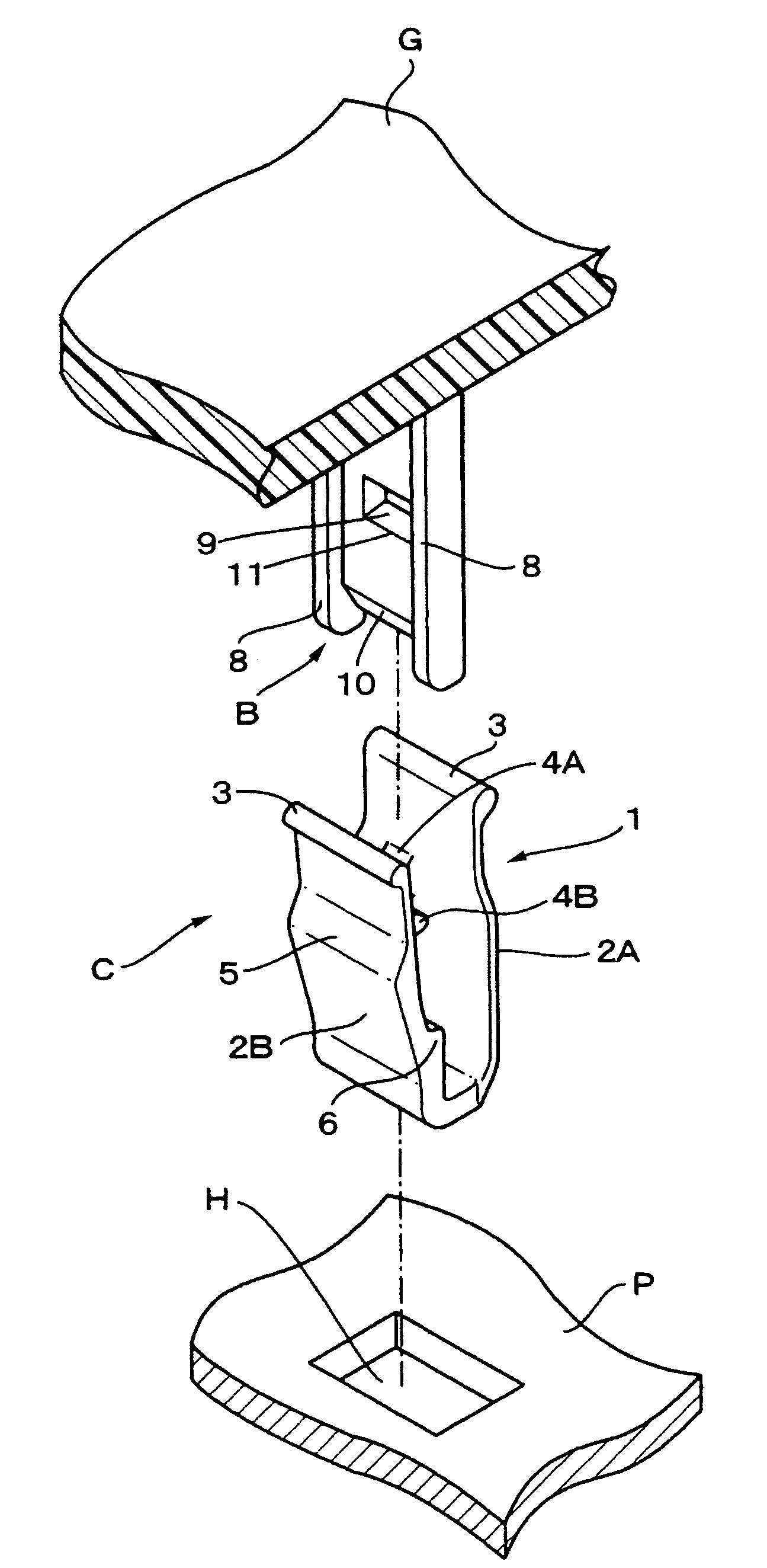
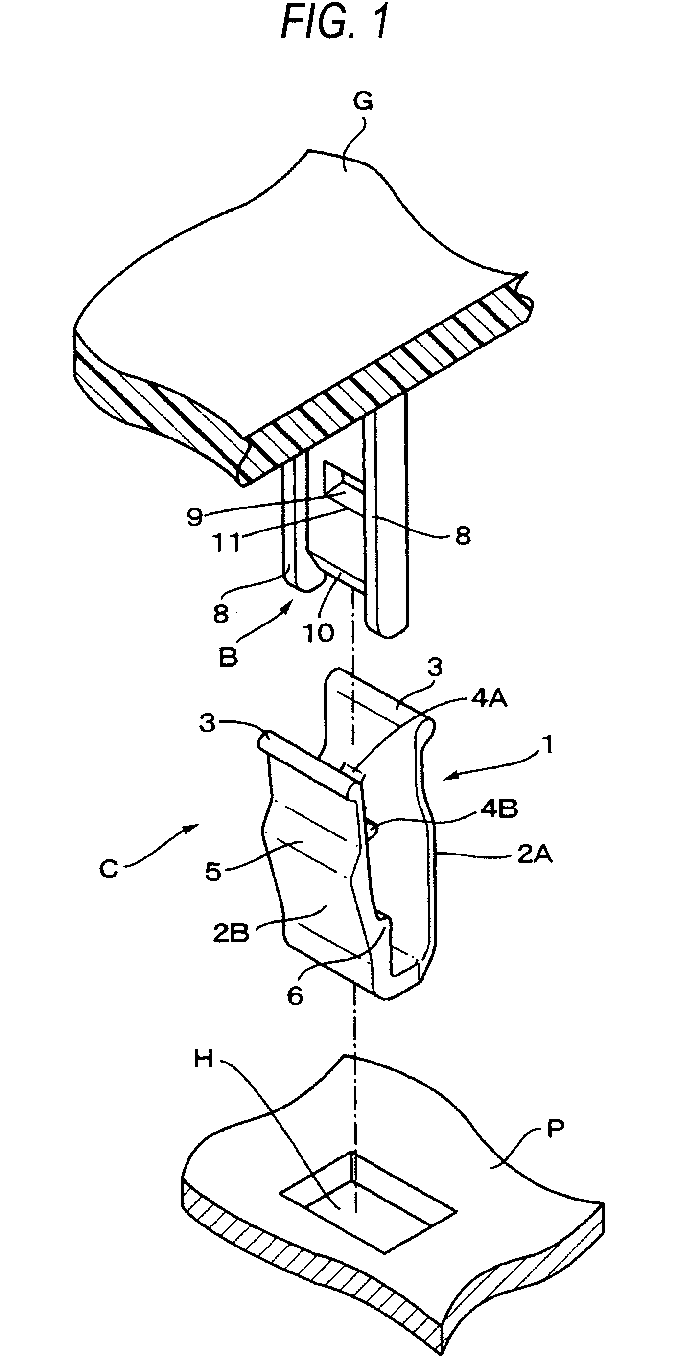
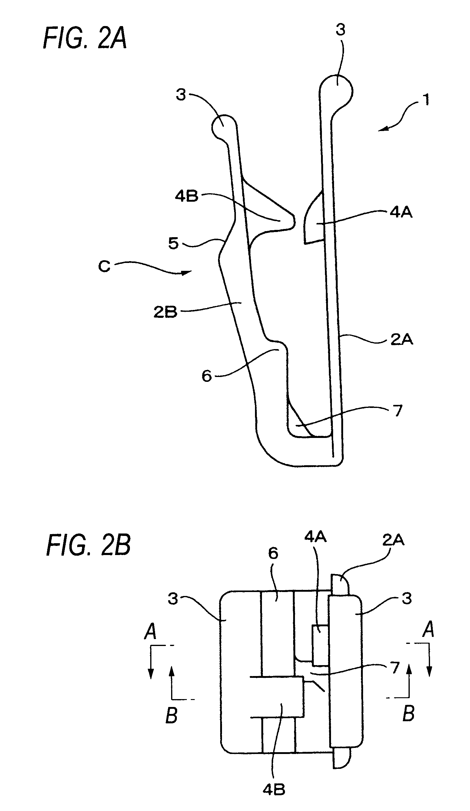
The present invention solves the problems of conventional mounting structures for vehicle interior materials by providing a new structure that improves mounting accuracy and prevents the clip from disengaging from the boss part. The new structure includes a clip with a U-shaped body and an engaging piece formed on the inner surface of the U-shaped body. The clip has a mounting hole punched through the vehicle body and a boss part protruding from the vehicle interior material. The engaging piece on the one sidewall of the U-shaped body faces the boss part and is formed lower than the engaging piece on the other sidewall. The clip is inserted into the mounting hole of the vehicle body and the other sidewall is bent inward, locking the clip securely. The engaging piece on the one sidewall is formed lower than the engaging piece on the other sidewall to make it easier to insert the clip. The lower inner surface of the engaging hole is inclined to catch the engaging piece on the one sidewall, ensuring secure engagement. The new structure improves mounting accuracy and prevents the clip from disengaging from the boss part.

Problems solved by technology

Therefore, there is a problem that a large force may be required to perform a work.

Method used


Image

  • Mounting structure of vehicle interior material
  • Mounting structure of vehicle interior material
  • Mounting structure of vehicle interior material

Examples


Embodiment Construction

[0028]In the invention, one sidewall forming the U-shaped body of the clip closely faces the boss part of the vehicle interior material, and the other sidewall forming the U-shaped body of the clip the other sidewall forming the U-shaped body faces the other surface of the boss part with a space therebetween. Further, an engaging piece to be engaged with an engaging hole provided on the boss part is formed on the inner surface of the one sidewall, an engaging piece that faces the engaging hole provided on the boss part is formed on the inner surface of the other sidewall, and an inclined shoulder to be locked by an edge of the mounting hole is form on the upper outer surface of the other sidewall. Accordingly, it is possible to easily insert the boss part into the U-shaped body and to effectively prevent the clip from being disengaged from the boss part.

[0029]Hereinafter, the invention will be described in detail with reference to a preferred embodiment. As well as the related art, ...


PUM


Abstract

A mounting structure of a vehicle interior material, includes: a boss part protruded from a rear surface of a vehicle interior material; a clip which has a U-shaped body; a mounting hole punched through the vehicle body; a first engaging piece to be engaged with an engaging hole provided on the boss part; a second engaging piece that faces the engaging hole; and an inclined shoulder to be locked by an edge of the mounting hole, wherein: the vehicle interior material is mounted on a vehicle body by locking the boss part in the mounting hole; the first engaging piece is formed on an inner surface of one sidewall, and the second engaging piece is formed on an inner surface of the other sidewall of the U-shaped body; and the inclined shoulder is form on the upper outer surface of the other sidewall.

Description

BACKGROUND OF THE INVENTION[0001]1. Field of the Invention[0002]The present invention relates to a mounting structure for mounting a vehicle interior material such as a resin garnish on a vehicle body.[0003]2. Description of the Related Art[0004]Although not shown in detail in a conventional mounting structure, a boss part is integrally formed to a rear surface of a vehicle interior material so as to protrude from the rear surface, and the vehicle interior material is mounted on a vehicle body by locking the boss part in a mounting hole punched through the vehicle body via a clip. In this respect, the clip used in the conventional mounting structure is an integrated molding part made of a synthetic resin, and includes a U-shaped body. One sidewall forming the U-shaped body is molded in a straight shape such that an engaging piece is formed on the inner surface thereof. The engaging piece is engaged with the engaging hole formed on the boss part. Further, the other sidewall forming t...

Claims


Application Information

Patent Timeline
Patent Type & Authority Patents(United States)
IPC IPC(8): E04F19/02F16B5/06F16B5/12
CPCB60R13/0206F16B5/0657F16B5/0664Y10T24/309Y10T24/42
Inventor ASANO, KAZUNORI
Owner PIOLAX CO LTD
Learn More