
Equalizing lumbar orthosis

a technology of lumbar orthosis and equalization, applied in the field of back braces and lumbar orthotics, can solve problems such as further complicatedness

Active Publication Date: 2008-11-11
WOLANSKE WALTER J
View PDF7 Cites 40 Cited by
  • Summary
  • Abstract
  • Description
  • Claims
  • Application Information

AI Technical Summary

Benefits of technology

[0011]Accordingly, the general object of the invention is to provide an improved back brace.
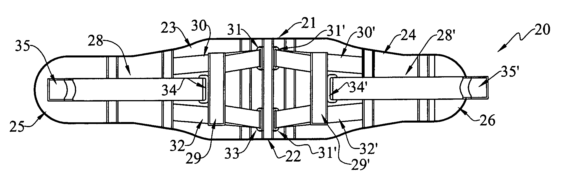
[0012]Another object is to provide an improved back brace that is automatically self-adjusting and force-equalizing in the sense that the upper and lower portions will be placed under equal tensile loads by the simple action of a pulling a pull strip.
[0013]Still another object is to provide an improved back brace that will self-adjust to exert substantially equal forces on the upper and lower portions independently of the position of the wearer's torso (i.e., whether standing or sitting).

Problems solved by technology

Thus, it is possible for the upper portion of the brace to be tightened more than the lower portion, and this is further complicated when the wearer stands or sits.

Method used


Image

  • Equalizing lumbar orthosis
  • Equalizing lumbar orthosis

Examples


Embodiment Construction

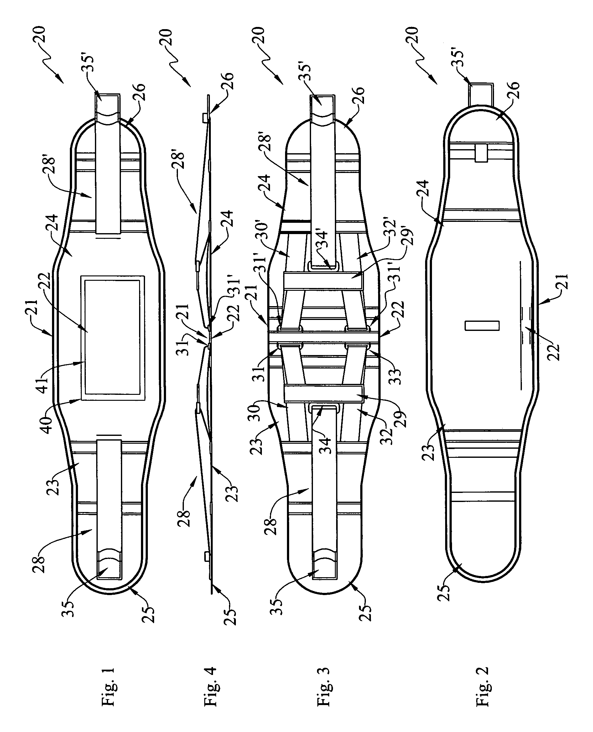
[0019]At the outset, it should be clearly understood that like reference numerals are intended to identify the same structural elements, portions or surfaces consistently throughout the several drawing figures, as such elements, portions or surfaces may be further described or explained by the entire written specification, of which this detailed description is an integral part. Unless otherwise indicated, the drawings are intended to be read (e.g., cross-hatching, arrangement of parts, proportion, degree, etc.) together with the specification, and are to be considered a portion of the entire written description of this invention. As used in the following description, the terms “horizontal”, “vertical”, “left”, “right”, “up” and “down”, as well as adjectival and adverbial derivatives thereof (e.g., “horizontally”, “rightwardly”, “upwardly”, etc.), simply refer to the orientation of the illustrated structure as the particular drawing figure faces the reader. Similarly, the terms “inwa...


PUM


Abstract

An equalizing back brace (20) is adapted to be worn by a person. The back brace includes a band (21) adapted to encircle the wearer's torso. The band has a rear portion (22) adapted to be positioned proximate the spine of a wearer, has side portions (23, 24) extending away from the rear portion at opposite directions, and has marginal end portions (25, 26) that are adapted to overlap one another proximate the front of such wearer. These marginal end portions are adapted to be selectively secured to one another to complete and close a band which encircles the wearer's torso. Two tightening mechanisms (28, 28′) are mounted on the side portions of the band. Each tightening mechanism has an intermediately-pivoted member (29, 29′), has an upper trace (30, 30′) secured to the band and engaging an upper marginal end portion of the member, and has a lower trace (32, 32′) secured to the band and engaging a lower marginal end portion of the member. A pull strip (35, 35′) is mounted on the band, and engages an intermediate portion of the member. The pull strip is adapted to be secured to the associated side portion at any of a plurality of positions relative thereto. Either or both side of the pull strips may be grasped, and pulled away from the rear portion, and secured to the band to selectively tighten the band about the wearer's torso.

Description

TECHNICAL FIELD[0001]The present invention relates generally to the field of back braces and lumbar orthotic devices, and, more particularly, to an improved back brace that can be quickly and easily tightened, and that automatically equalizes the forces exerted on the upper and lower portion of the brace independently of whether the wearer is standing or sitting.BACKGROUND ART[0002]Many people suffer from back pain. There are many possible causes of this pain. In some cases, the pain may be reduced or alleviated by a suitable brace or support. Back braces are certainly known.[0003]One such prior art brace is shown in U.S. Pat. No. 7,001,348. This reference discloses an adjustable back brace with a rear portion, two side portions, and overlapable marginal end portions. Two pull tabs are adjustably mounted on each of the side portions, and are used to selectively tighten upper and lower cords at the rear of the brace. The pull tabs may be operated separately to adjust the cords indepe...

Claims


Application Information

Patent Timeline
Patent Type & Authority Patents(United States)
IPC IPC(8): A61F5/00
CPCA61F5/028
Inventor WOLANSKE, WALTER J.
Owner WOLANSKE WALTER J
Learn More