Camber/caster gauge
- Summary
- Abstract
- Description
- Claims
- Application Information
AI Technical Summary
Benefits of technology
Problems solved by technology
Method used
Image
Examples
Example
DETAILED DESCRIPTION OF THE DRAWINGS
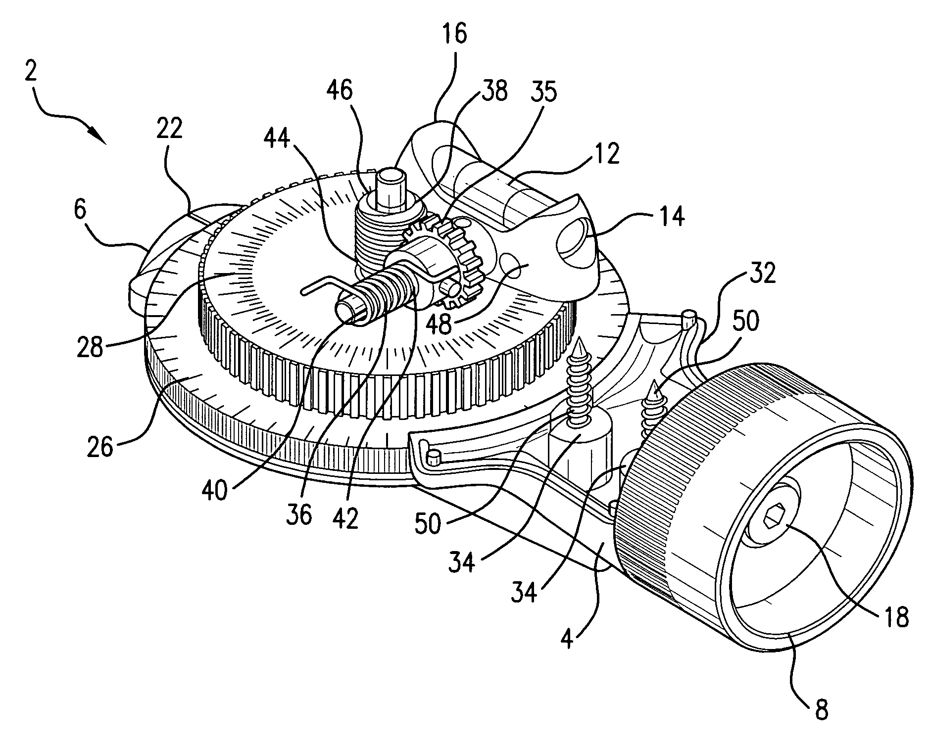
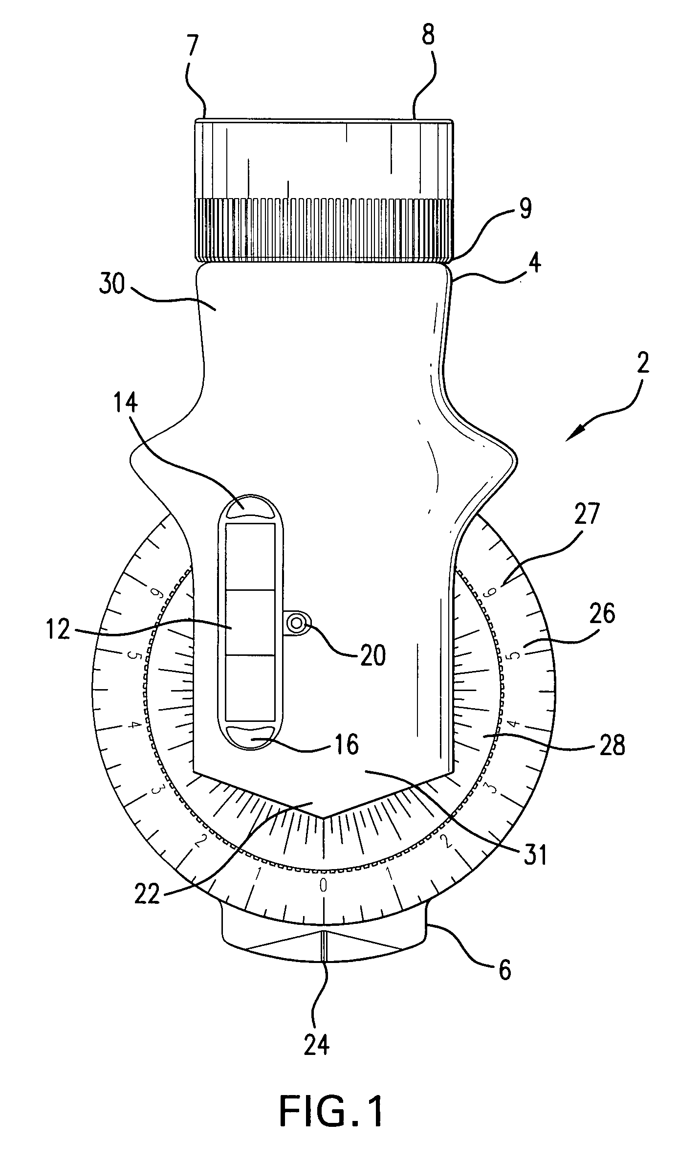
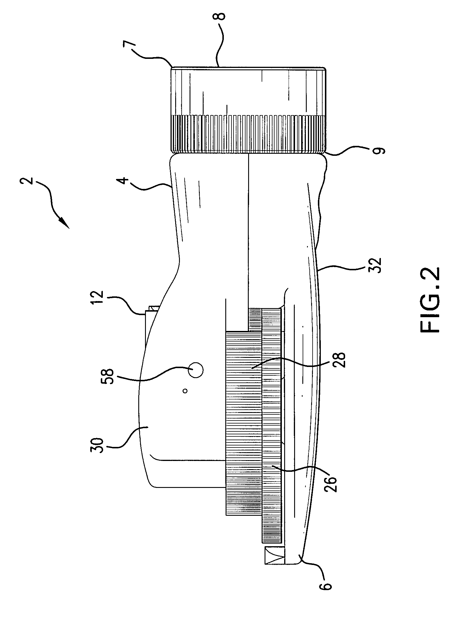
[0019]FIG. 1 is a full top view of the camber / caster gauge 2 showing the near end 4 and the distal end 6. The near end 4 is attached to a threaded adaptor 8. The threaded adaptor 8 has a near end 7 and a distal end 9. The threaded adaptor 8 is attached to the near end 4 of the camber / caster gauge 2 at its distal end 9 via the adaptor connector 18, (not shown). The near end 7 of the threaded adaptor 8 is the end that attaches the caster / camber gauge to the axle of a wheeled vehicle. In this figure the straight vial level 12 is shown. The straight vial level 12 is mounted within a top housing 30. The straight vial level 12 has a near end 14 and a distal end 16. Also shown in this Figure is the attachment point 20 of the straight vial level 12, to the pivotal shaft 54 (not shown). The camber measurement (large dial) 26 is shown wherein the graduation 27 of the camber dial 26 that is measured in degrees and minutes. The camber dial 26 graduation scale...
PUM
 Abstract
Description
Claims
Application Information
 - R&D
- Intellectual Property
- Life Sciences
- Materials
- Tech Scout
- Unparalleled Data Quality
- Higher Quality Content
- 60% Fewer Hallucinations
Browse by: Latest US Patents, China's latest patents, Technical Efficacy Thesaurus, Application Domain, Technology Topic, Popular Technical Reports.
© 2025 PatSnap. All rights reserved.Legal|Privacy policy|Modern Slavery Act Transparency Statement|Sitemap|About US| Contact US: help@patsnap.com


