
Multi-display apparatus having an optical path changing device

a multi-display and optical path technology, applied in the field of multi-display apparatuses, can solve problems such as deteriorating image quality

Inactive Publication Date: 2008-10-21
SAMSUNG ELECTRONICS CO LTD
View PDF15 Cites 19 Cited by
  • Summary
  • Abstract
  • Description
  • Claims
  • Application Information

AI Technical Summary

Benefits of technology

The present invention provides a multi-display apparatus with a plurality of flat panel display devices connected to each other, which displays an image without a non-display area on a screen. The apparatus includes an optical path changing unit with an inclined surface symmetrical to the boundary surface of the flat panel display devices, which shifts light emitted from the flat panel display devices toward the boundary surface. The optical path changing unit can be a triangular prism array or a wave guide array. The technical effect of the invention is to improve the image quality and viewing experience of the multi-display apparatus.

Problems solved by technology

Accordingly, the non-display area where the image is not displayed divides the image and lowers a resolution thereof, thus, deteriorating the image quality.

Method used


Image

  • Multi-display apparatus having an optical path changing device
  • Multi-display apparatus having an optical path changing device
  • Multi-display apparatus having an optical path changing device

Examples


Embodiment Construction

[0036]Reference will now be made in detail to the embodiments of the present invention, examples of which are illustrated in the accompanying drawings, wherein like reference numerals refer to like elements throughout. The embodiments are described below in order to explain the present invention by referring to the figures.

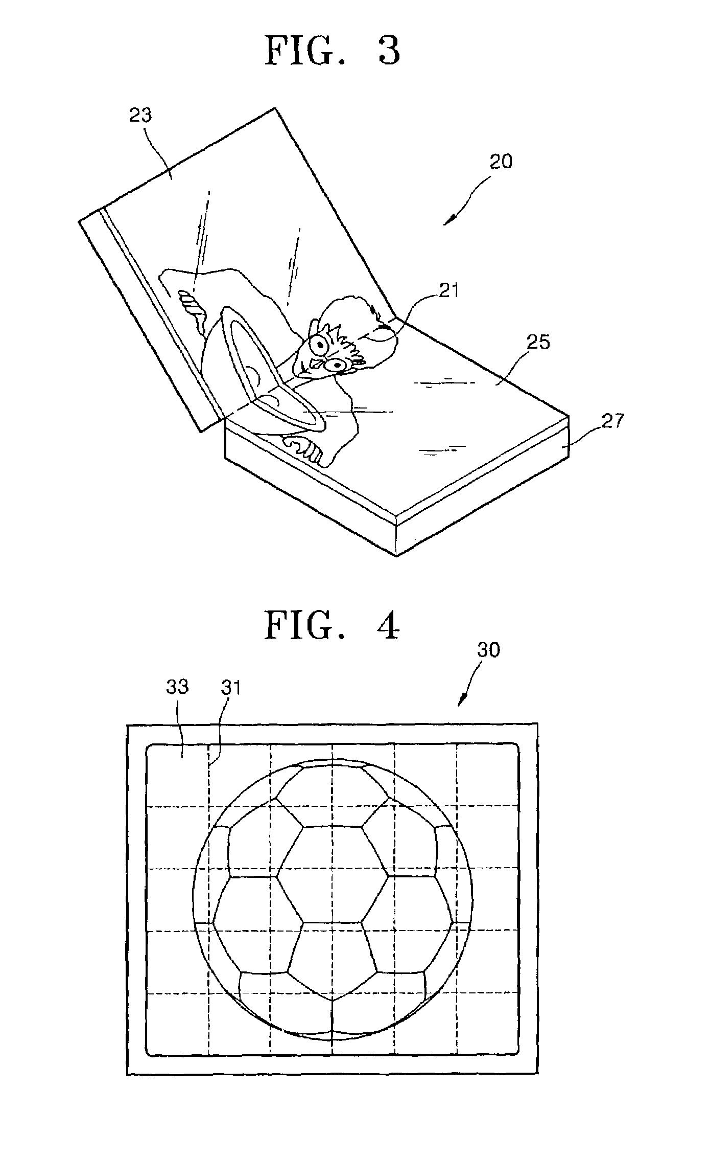
[0037]Referring to FIG. 3, a folding type display apparatus 20 of a multi-display apparatus, according to an aspect of the present invention, includes two screens 23 and 25, one side of the screen 23 contacting an adjacent side of the screen 25, and a main body 27 disposed at a lower surface of each of the screens 23 and 25. Two flat panel display devices (not shown) are connected inside the main body 27 and a connection portion remains as a light shield area which does not transmit light. In the present invention, an optical path changing device (to be shown in FIGS. 5A-10B) is arranged on an upper surface of the flat panel display devices including a connection ...


PUM

PropertyMeasurementUnit
inclination angleaaaaaaaaaa
refractive indexaaaaaaaaaa

Abstract

A multi-display apparatus includes flat panel display devices and an optical path changing unit. The flat panel display devices include adjacent sides connected to each other. The optical path changing unit has an inclined surface symmetrical to a boundary surface of the flat panel display devices and shifting light emitted from the flat panel display devices toward a boundary surface between the flat panel display devices to display an image without a non-display area.

Description

CROSS-REFERENCE TO RELATED APPLICATIONS[0001]This application claims the benefit of Korean Application No. 2002-33725, filed Jun. 17, 2002, in the Korean Intellectual Property Office, the disclosure of which is incorporated herein by reference.BACKGROUND OF THE INVENTION[0002]1. Field of the Invention[0003]The present invention relates to a multi-display apparatus having a plurality of flat panel display devices, and more particularly, to a multi-display apparatus which provides an image without a non-display area.[0004]2. Description of the Related Art[0005]A multi-display apparatus is defined as a display apparatus forming one screen area by connecting a plurality of flat panel display devices. Of the multi-display apparatuses, a folding type display apparatus is often used for a portable device such as a notebook computer, while a large screen display apparatus is widely used as a display in a stadium, for instance, or as an advertisement display elsewhere.[0006]FIG. 1 shows a co...

Claims


Application Information

Patent Timeline
Patent Type & Authority Patents(United States)
IPC IPC(8): G09G5/00G02F1/1335G02B5/04G02F1/13G02F1/1333G02F1/13357G09F9/00G09F9/40H01L51/50H05B33/02H05B33/14
CPCG02B5/045G02F1/13336G02F1/133526G02F2001/133562G02F1/133562G02F1/1335
Inventor CHO, KUN-HOKIM, DAE-SIKLEE, HEE-JOONGKIM, TAE-HEE
Owner SAMSUNG ELECTRONICS CO LTD
Learn More