
Systems and methods for explosive blast wave mitigation

a technology of explosive blast wave and mitigation system, which is applied in the field of mitigation can solve the problems of toxic to humans, all prior art mitigation methods for reducing the damage affecting the damping effect of explosive blast wave, so as to improve the damping effect of shock wav

Active Publication Date: 2008-09-09
RAYTHEON BBN TECH CORP
View PDF15 Cites 20 Cited by
  • Summary
  • Abstract
  • Description
  • Claims
  • Application Information

AI Technical Summary

Benefits of technology

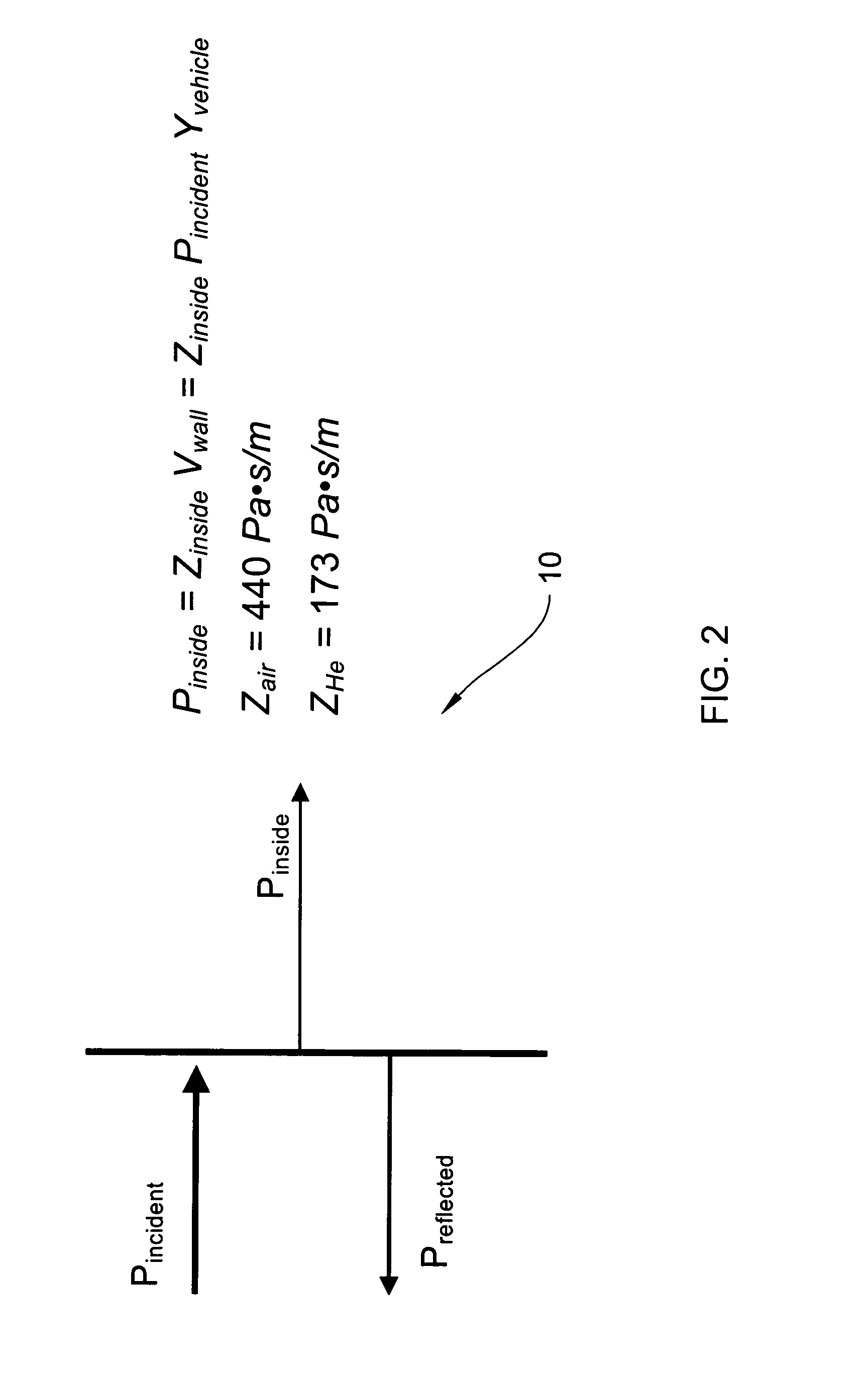
[0014]In one embodiment, the invention detects an explosion external to the contained environment using, for example, ultraviolet and / or infrared detectors. In response to detecting such an explosion, the invention releases a gas having specific acoustic impedance less than air into the substantially contained environment. Preferably, the volume of the gas is sufficient to fill substantially the environment. Since the pressure inside the environment directly relates to the specific acoustic impedance of the gas that fills it, the newly introduced gas reduces a peak overpressure that can occur in as a result of the shock wave. More particularly, the peak overpressure in the environment is reduced by a factor of one minus the ratio of the specific acoustic impedance of the introduced gas to specific acoustic impedance of air. Subsequent to the shock wave passing, the invention vents the introduced gas and provides clean air back into the environment.
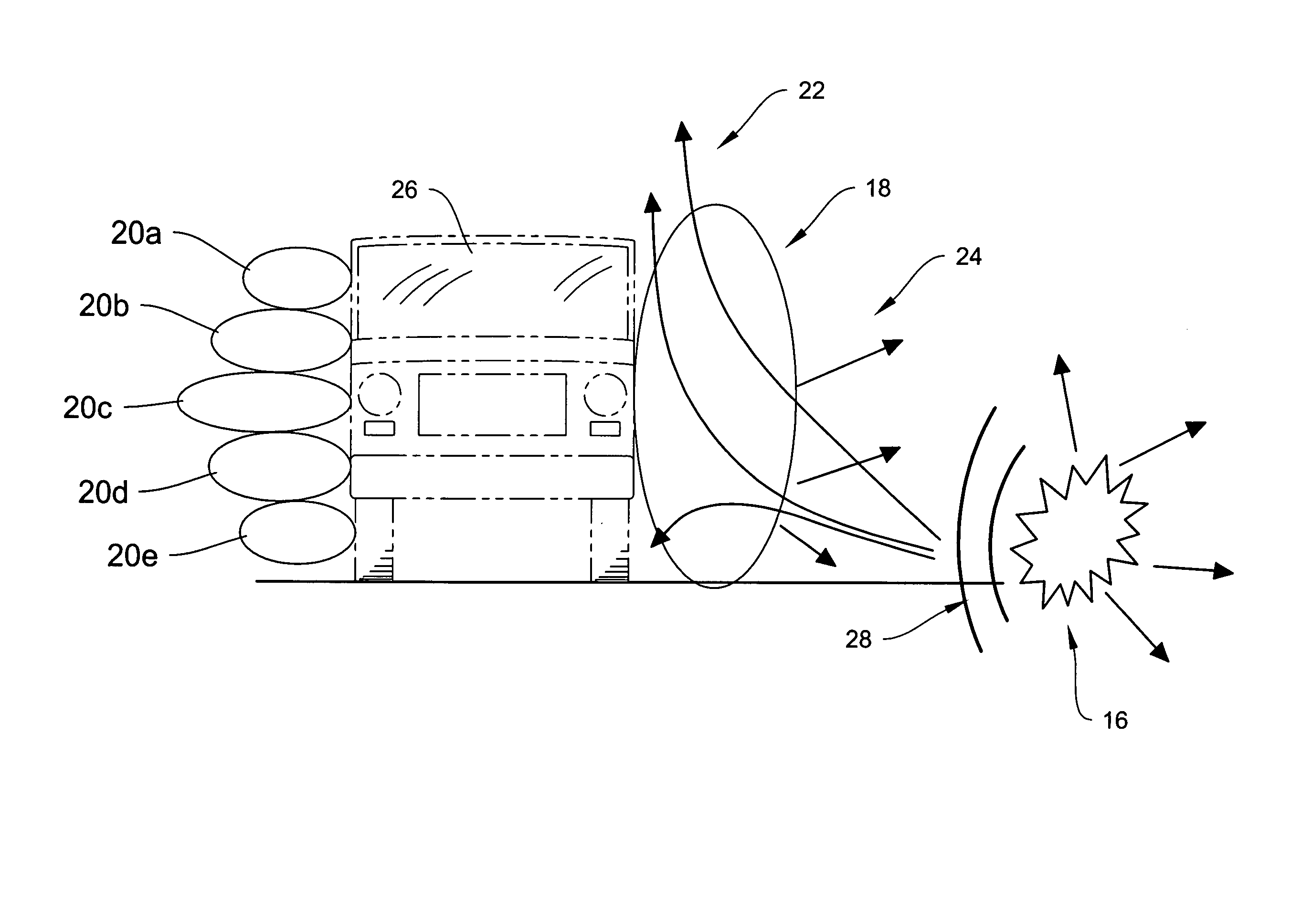
[0016]According to another aspect, the invention mitigates damage to a target, in general, from a shock wave caused by an explosion. The target may be, for example, a land, air or water vehicle, or a building, both large and small and both permanent and portable in nature. According to one embodiment, the invention interposes a convex gas lens between an explosion and the target to deflect, diffract, disburse or otherwise direct the shock wave away from the target.
[0019]According to other embodiments, the lens bladders are maintained in an inflated state. In these embodiments, explosion detection is not necessarily needed, nor is any valve mechanism for automatically releasing the lens gas in response to such detection. An advantage of this configuration is that time is not lost releasing the gas. Additionally, the lens gas is warmer if it has not just been quickly released into the bladder, and the warmer gas provides improved shock wave damping characteristics.

Problems solved by technology

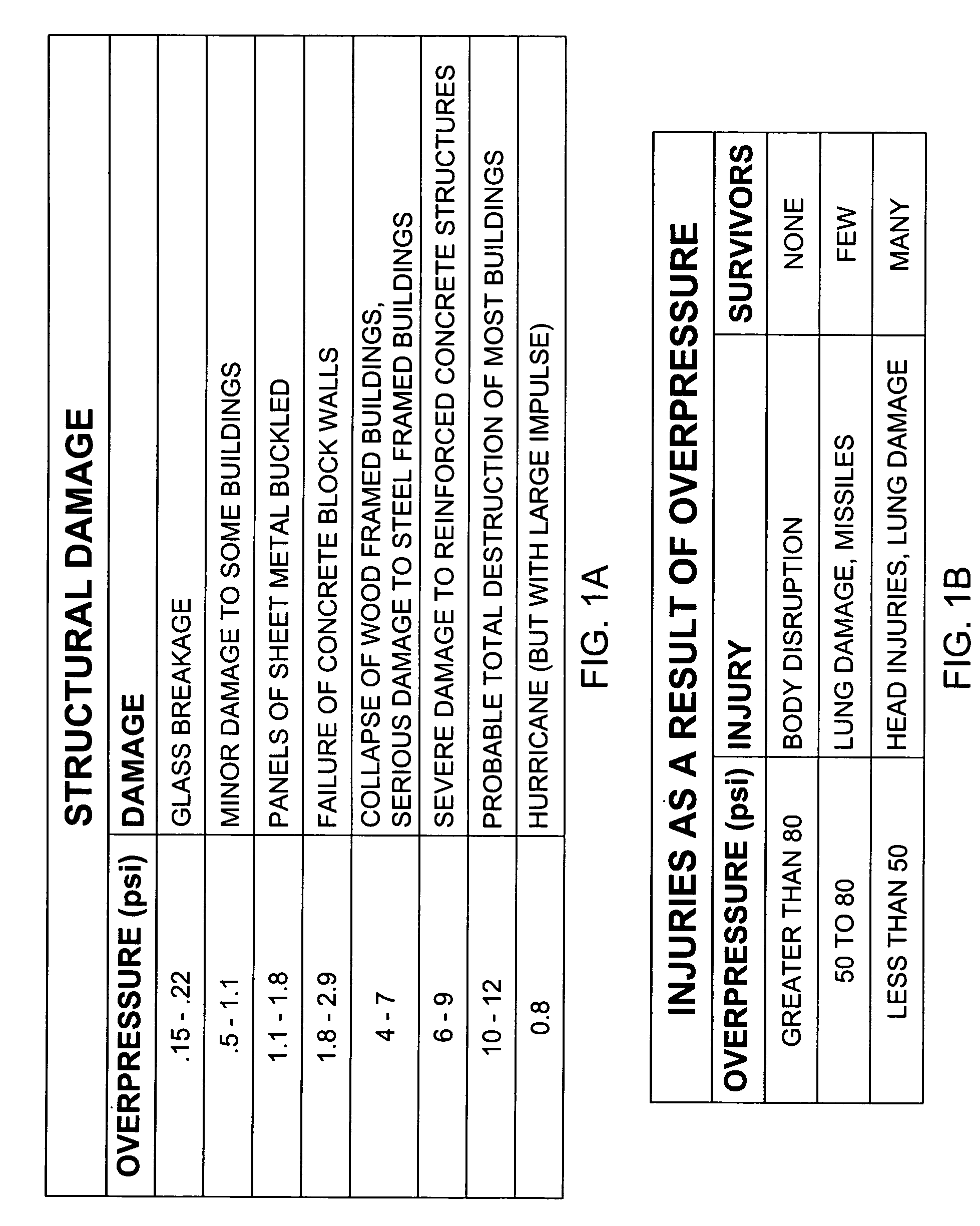
Shock waves can cause significant damage to both humans and mechanical structures.
The overpressure caused by a shock wave is one source of such damage.
All of the prior art approaches for shock wave mitigation suffer from significant drawbacks, such as being toxic to humans, too heavy, too bulky, not easily transportable, and not usable in a wide variety of applications.
Where protection of large areas from powerful shock effects is necessary, structures must be massive and are thus inherently immobile, expensive and time consuming to erect.
A disadvantage of blast mats is that they are heavy and bulky.
When not being used, they require large amounts of storage, and due to their weight and bulk are not easily moved from storage to a location where they are needed.
Venting does not provide protection from a blast originating in an open, uncontained environment.
Venting also cannot be employed where hazardous materials may be released, and does not provide significant shock wave attenuation.
However, chemical agents currently available for fire and explosion suppression typically have toxic effects upon humans at the concentrations required to be effective.
Also, aside from removing the source of the shock wave, they do not provide any significant attenuation for the shock wave caused by the initial explosion.
Additionally, shock waves propagating through aqueous foams create turbulent flow fields, which also dissipates substantial amounts of energy, particularly when reflected waves travel through the turbulent medium.
One drawback of aqueous foam is that it requires a foam generation system and / or a large bulky supply of foam to be stored wherever it is to be deployed.
However, solid foams have proven not to be as effective as aqueous foams at attenuating shock waves.
However, the solid bead approach suffers from the drawback that it is typically employed with a solid rigid frame for containing the beads, foam or a combination thereof.
Because prior art approaches to shock wave attenuation suffer from significant deficiencies, including being too heavy, not being easily transportable, taking up too much storage, they are not practical for many applications where explosion hazards are present, such as, battle field conditions where structures need to be easily erected, dismantled and transported.
The deficiencies also render them impractical for personal body protection for soldiers, and for motor vehicle protection.

Method used


Image

  • Systems and methods for explosive blast wave mitigation
  • Systems and methods for explosive blast wave mitigation
  • Systems and methods for explosive blast wave mitigation

Examples


Embodiment Construction

[0040]As described above in summary, the invention generally relates to mitigating damage done by shock waves caused by an explosion. As such, the invention has particular application to transfer and storage of explosive substances; battle field protection, including personal, vehicle and building; and protection against terrorist attacks. According to various illustrative embodiments, the invention is directed to systems and methods that substantially fill a contained or substantially contained environment with a gas having specific acoustic impedance (Z) less than the specific acoustic impedance of air to reduce peak overpressure within the environment. In other illustrative embodiments, the invention is directed to systems and methods that interpose a low impedance gas lens between an explosion and a target to be protected. In some implementations, the environment gas filling features and the interposed gas lens features are combined into a comprehensive system for mitigating dam...


PUM


Abstract

The invention in various embodiments is directed to systems and methods for mitigating damage from a shock wave using a gas having a specific impedance less than air.

Description

FEDERALLY SPONSORED RESEARCH[0001]The inventions described herein were made with government support under DARPA Contract Number HR0011-04-C-0086. Accordingly, the government may have certain rights in the inventions.FIELD OF THE INVENTION[0002]The invention generally relates to mitigating shock waves. More particularly, in various embodiments, the invention is directed to systems, methods and devices employing an acoustic lens for mitigating the shock waves from an explosion.BACKGROUND[0003]Shock waves are traveling pressure fluctuations that cause local compression of the material through which they travel. When traveling through a gas, such as air, shock waves produce increases in pressure, referred to as “overpressure”, along with increases in temperature. They also accelerate gas molecules and entrained particulates in the direction of shock wave travel. Shock waves produced by explosions also release substantial amounts of thermal and radiant energy.[0004]Shock waves can cause ...

Claims


Application Information

Patent Timeline
Patent Type & Authority Patents(United States)
IPC IPC(8): F41H11/00
CPCF41H5/007F41H5/08F42D5/045F41H9/04F41H5/24
Inventor BARGER, JAMES E.HAMEL, DANIEL L.
Owner RAYTHEON BBN TECH CORP
Learn More