
Connector structure

a technology of connecting parts and connectors, applied in the direction of coupling device connection, coupling parts engagement/disengagement, incorrect coupling prevention, etc., can solve the problems of failure of the connector connector constituent members and failure of the fitting mechanism

Inactive Publication Date: 2008-09-02
YAZAKI CORP
View PDF4 Cites 24 Cited by
  • Summary
  • Abstract
  • Description
  • Claims
  • Application Information

AI Technical Summary

Benefits of technology

The invention is a connector structure that allows for easy fitting and cancellation of connectors with a low inserting force. It includes a locking arm with an engagement portion and a lever for performing fitting and cancellation operations. The lever has an operation access portion that can be pressed to cancel the fitting of the connectors. The operation access portion is positioned in a way that it can be pressed before the cancellation operation, allowing for a continuous operation of the lever. The lever can also have an opening for easy access by an operator's finger. The connector structure provides a simple and effective way to cancel the fitting of connectors.

Problems solved by technology

Therefore, there were caused problems that the operating procedure became complicated and troublesome and that there was caused a fear that due to the complicated and troublesome operating procedure, a failure to follow the operating procedure would occur, which would trigger a failure of constituent members of the connectors.
Namely, for example, when the fitting of the connectors was canceled by the lever while having failed to perform the canceling operation of the fitting by the fitting mechanism of the connectors, there was a fear that the fitting mechanism would fail by virtue of the toggle effect of the lever.

Method used


Image

  • Connector structure
  • Connector structure
  • Connector structure

Examples


Embodiment Construction

[0034]Hereinafter, the invention will be described by reference to an embodiment which is illustrated in the accompanying drawings.

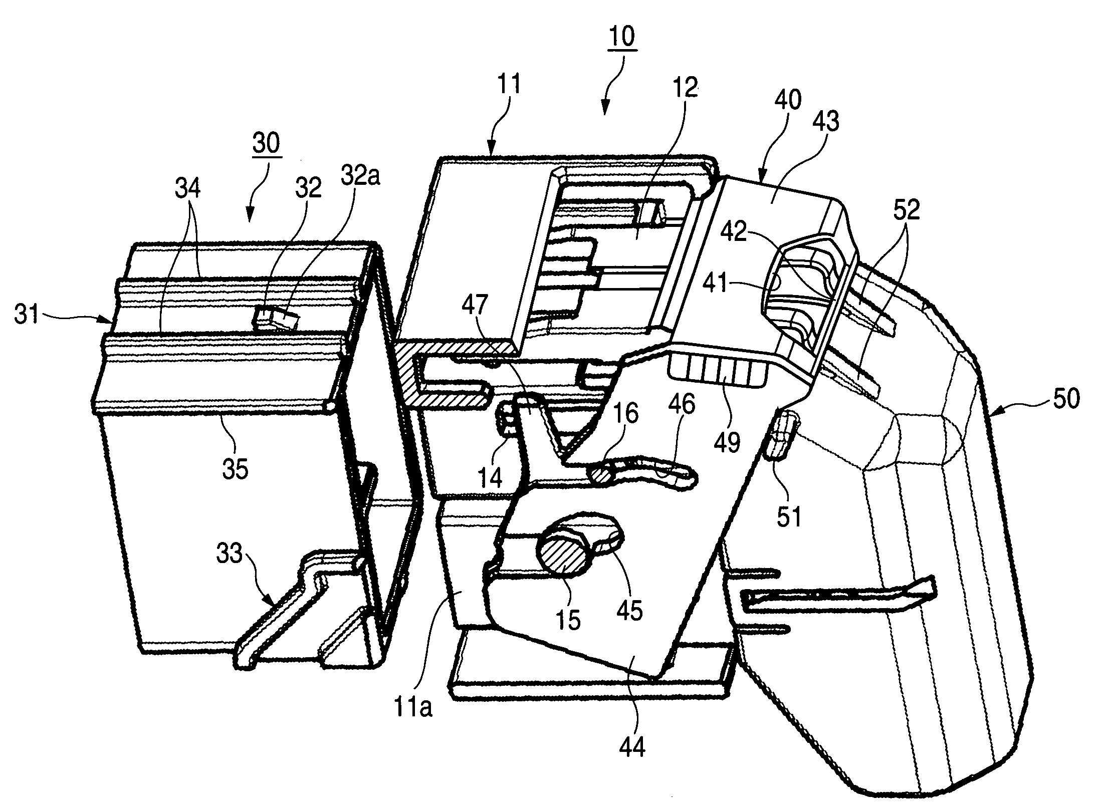
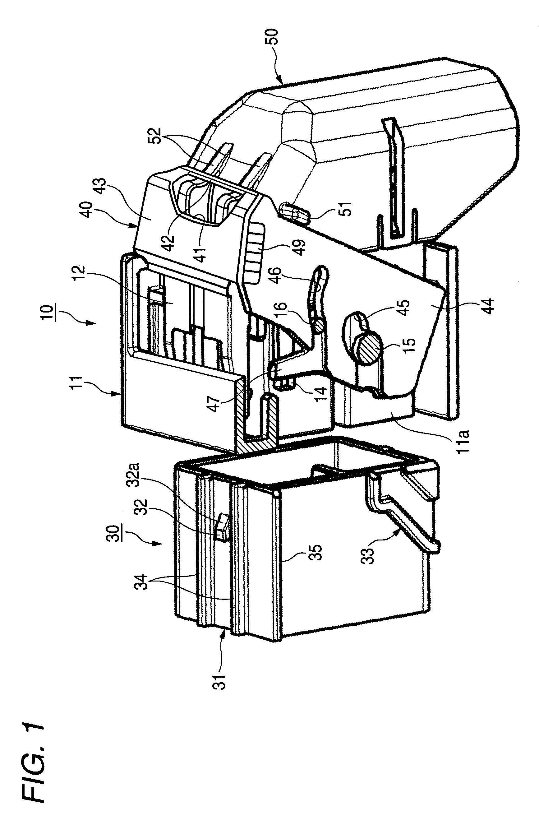
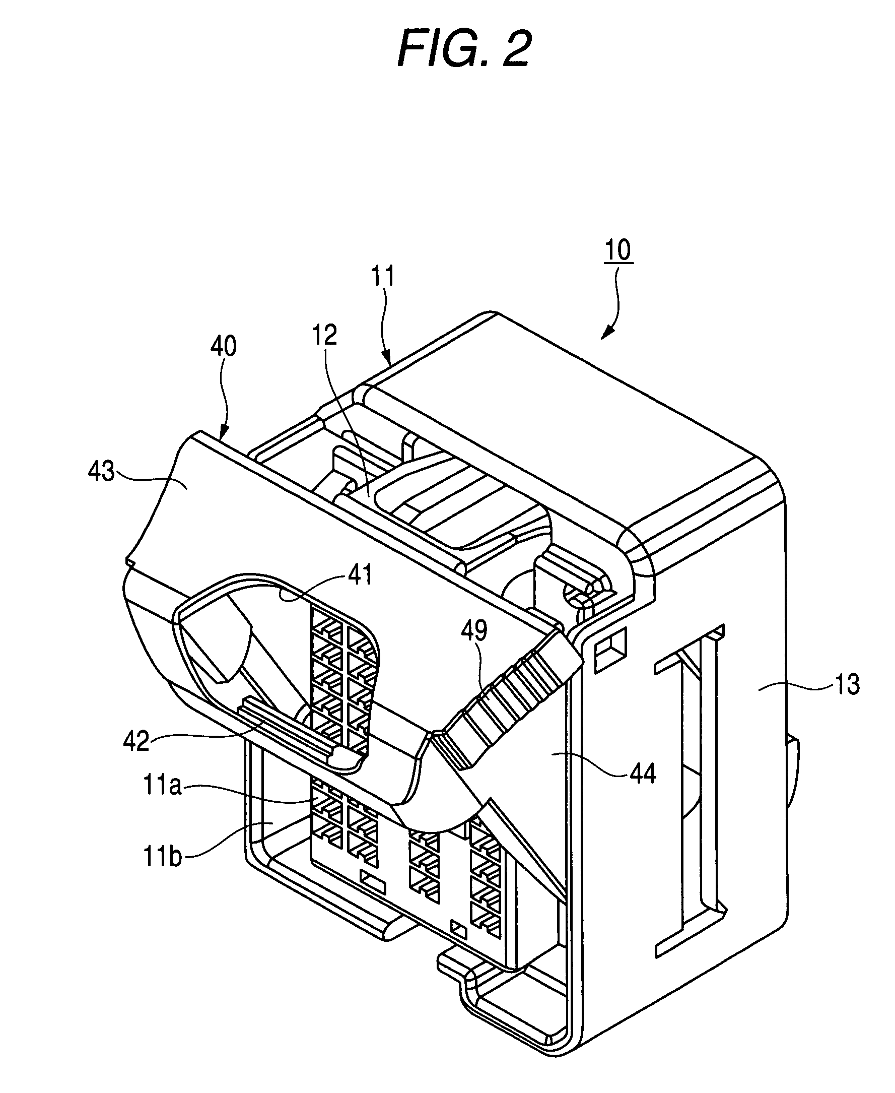
[0035]FIG. 1 is a perspective view of a connector structure according to an embodiment of the invention with an outer housing removed therefrom which shows a state in which a male connector has not yet been fitted in a female connector, and FIG. 2 is a perspective view of the female connector of the connector structure in FIG. 1 which shows a state resulting before a lever thereof performs a fitting operation.

[0036]In addition, FIG. 3 is a sectional view of the connector structure shown in FIG. 1 with the cover removed therefrom and the male connector fitted in the female connector which shows a sectional view taken in a position where a locking arm becomes visible such that the lever has performed the fitting operation, FIG. 4 is a perspective view of the connector structure shown in FIG. 3, FIG. 5 is a sectional view showing a state in which the lockin...


PUM


Abstract

A lever is rotatably mounted on an inner housing of a female connector and assists a fitting operation through engagement of an engagement portion of a locking arm of the female connector with an engagement projection of a male connector and a fitting canceling operation in association with rotation thereof. An opening in the lever allows the tip of a finger of an operator to be brought into contact with an operation access portion of the locking arm so as to press the operation access portion, and a lever locking canceling finger catch portion of the lever is located in a position and formed into a shape which allow the finger of the operator to be hooked thereon such that the tip of the finger is in contact with the operation access portion of the locking arm.

Description

BACKGROUND OF THE INVENTION[0001]1. Field of the Invention[0002]The present invention relates to a connector structure in which a pair of male and female connectors are fitted together.[0003]2. Related Art[0004]Conventionally, lever type connectors have been known (refer to, for example, JP-A-9-120859). FIG. 10 is an exploded perspective view which shows a lever type connector disclosed in JP-A-9-120859.[0005]Referring to FIG. 10, in a lever type connector 100, a rotating lever 101 is supported on a connector main body 120 of a male side connector 110 in such a manner as to rotate about support pins 121 of the connector main body 120 by allowing the support pins 121 to be fitted in shaft holes 102 in the rotating lever 101.[0006]While assisting the connector main body 120 of the male side connector 110 in performing a fitting operation into a female side connector 130 as it rotates, the rotating lever 101 brings the individual connectors 110, 130 into a state where the connectors ar...

Claims


Application Information

Patent Timeline
Patent Type & Authority Patents(United States)
IPC IPC(8): H01R13/62
CPCH01R13/639H01R13/62955H01R13/62938
Inventor OHTAKA, KAZUTOKOJIMA, TAKASHITAKAHASHI, TOSHIHARU
Owner YAZAKI CORP
Learn More