
Multilumen unilimb breathing circuit with detachable proximal fitting

a multi-lumen, proximal fitting technology, applied in the direction of colloidal chemistry, separation process, filtration separation, etc., can solve the problems of unfavorable the proximal end of the inner tube could be disconnected from the inspiratory port, and the prior art unilimb devices do not facilitate the reconnection of the inner tube to the inspiratory port, etc., to reduce the possibility of component disconn

Inactive Publication Date: 2008-09-02
AMBU AS
View PDF74 Cites 52 Cited by
  • Summary
  • Abstract
  • Description
  • Claims
  • Application Information

AI Technical Summary

Benefits of technology

[0013]The present invention provides in one aspect an improved assisted or artificial ventilation system utilizing a unilimb device for providing and exhausting gases from a mammal, and, in another aspect, an artificial ventilation method which avoids hypocapnia and hypoxia. Further aspects of the present invention include new and improved devices for use in the ventilation methods and systems of the present invention.
[0014]Aspects of the present invention relate to the surprising discovery by the inventor that concerns about disconnection of the inner respiratory tube, when connected to the inspiratory port of a proximal terminal in breathing circuits utilizing a unilimb device, such as the UNIVERSAL F® circuit or the “Bain” circuit (U.S. Pat. No. 3,856,051), can be eliminated by the new proximal terminal construction of the present invention, which facilitates the use of tubing which is intentionally made to be readily attachable and detachable to the proximal terminal ports, rather than permanently sealably connected as in present systems, and yet provide improved function, safety, and serviceability. The breathing circuit manufacturing process is greatly simplified by eliminating the steps of sealably bonding the proximal ends of the inner and outer flexible respiratory tubes to the inspiratory and patient ports, respectively, of the unilimb proximal terminal. The new unilimb proximal terminal of the present invention facilitates the attachment and detachment of respiratory tubing to the proximal terminal, thus resulting in a cheaper and safer breathing circuit. The new unilimb proximal terminal also permits more efficient placement and utilization of the other breathing circuit components in a multifunctional interface incorporating the unilimb proximal terminal. In another aspect of the present invention, an improved coaxial tube device is provided, which is readily attachable and detachable from the new proximal terminal. The improved coaxial tube device has an inner tube in fixed spaced coaxial parallel relationship to an outer tube at its proximal end, such that a single step is required to connect both tubes to the proximal terminal. This is made possible by a fitting within or at the proximal ends of the coaxial inner and outer tubes, which still permits the distal end of the inner tube to axially move with respect to the distal end of the outer tube. As used herein, coaxial refers to the fact that one tube is contained within the other, but the central axis of both tubes need not be aligned.
[0015]Aspects of the present invention involve the surprising discovery by the inventor that hypoxia can be avoided while simultaneously creating intentional dead space in the breathing circuit, thereby increasing rebreathing of expired carbon dioxide, which enables maintenance of normal levels of arterial blood carbon dioxide (i.e., normocapnia) during artificial ventilation. Even more surprising is the discovery by the inventor that moderate hypercapnia will not cause hypoxia, provided sufficient oxygen reaches the patient; in fact, moderate hypercapnia can be beneficial to a patient (e.g., improve cardiovascular oxygen availability and tissue oxygenation). In yet another aspect of the present invention, the arterial blood carbon dioxide tension (PaCO2) can be predictably controlled via a predetermined dead space created in the unilimb device breathing tubes (i.e., the volume in the outer tube defined by the space between the outer tube distal end and the inner tube distal end). The dead space volume may be made adjustable by use of axially extendable and compressible corrugated tubing (which does not rebound to its prior length and maintains its approximate internal diameter despite bending and / or axial length changes); the tubing connects at its proximal end to the patient port of the proximal terminal, and may have dead space calibration markings thereon to permit determination and adjustment of dead space volume contained therein.

Problems solved by technology

However, manufacture of the entire unit requires several complex steps, and must be done with care so that the inner and outer tubes are properly sealed and bonded to the proximal terminal ports at their proximal ends; it is particularly important that the inner tube proximal end be firmly connected to the proximal terminal (at the inspiratory port) when the inner tube carries inspiratory gases, since disconnection during use may not allow sufficient oxygen and / or anesthetic gases to reach a patient, which is highly undesirable.
While U.S. Pat. No. 4,265,235, to Fukunaga, teaches that the tubes and terminals of such a unilimb device can be detachable from one another, in practice, the proximal end of the inner tube is firmly bonded to the inspiratory port, since there remains a risk that the proximal end of the inner tube could be disconnected from the inspiratory port during use if a pressure fit (or friction fit) alone is used.
Even if detachment of the inner tube is detected, the design of prior art unilimb devices does not facilitate the reconnection of the inner tube to the inspiratory port of the proximal terminal due to the need to pass the inner tube proximal end through the length of the proximal terminal via the patient port so that it can reach and be connected to the inspiratory port.
Thus, in addition to the inconvenience of requiring fittings (or a housing accommodating same) for these additional devices at the patient nozzle or distal terminal, replacement of these fittings, tubing, and devices after a single use is expensive, and contributes to ever-growing medical wastes, which are sometimes difficult to find disposal sites for.
All of the systems described in the aforementioned patents suffer from similar deficiencies.
Further, it is believed that devices sold for disposal after a single use may sometimes be reused in order to save costs, which may endanger patients.
One problem with this is that the exterior of the patient respiratory conduits, as well as the interior thereof, need to be protected from contamination, so that contaminants from a first patient do not get passed on to subsequent patients by adhering to the exterior of reused components.
However, the filter does not protect the exterior of the coaxial conduit from contamination.
Thus, patients are given very high inspired concentrations of oxygen to avoid hypoxia, but unfortunately they often experience abnormally low carbon dioxide levels (i.e., hypocarbia or hypocapnia), and insufficient carbon dioxide can have a negative impact on vital organs (e.g., brain, heart, splanchnic organs, etc.).
However, many physicians believe that increasing arterial carbon dioxide partial pressure (PaCO2, also referred to as arterial carbon dioxide tension, often reported as mmHg) in patients by increasing the carbon dioxide breathed by the patient (e.g., by increasing the amount of rebreathing) would cause hypoxia.
Thus, it was believed that hypercapnia during assisted ventilation was harmful, since it was believed it would be associated with hypoxia.

Method used


Image

  • Multilumen unilimb breathing circuit with detachable proximal fitting
  • Multilumen unilimb breathing circuit with detachable proximal fitting
  • Multilumen unilimb breathing circuit with detachable proximal fitting

Examples


Embodiment Construction

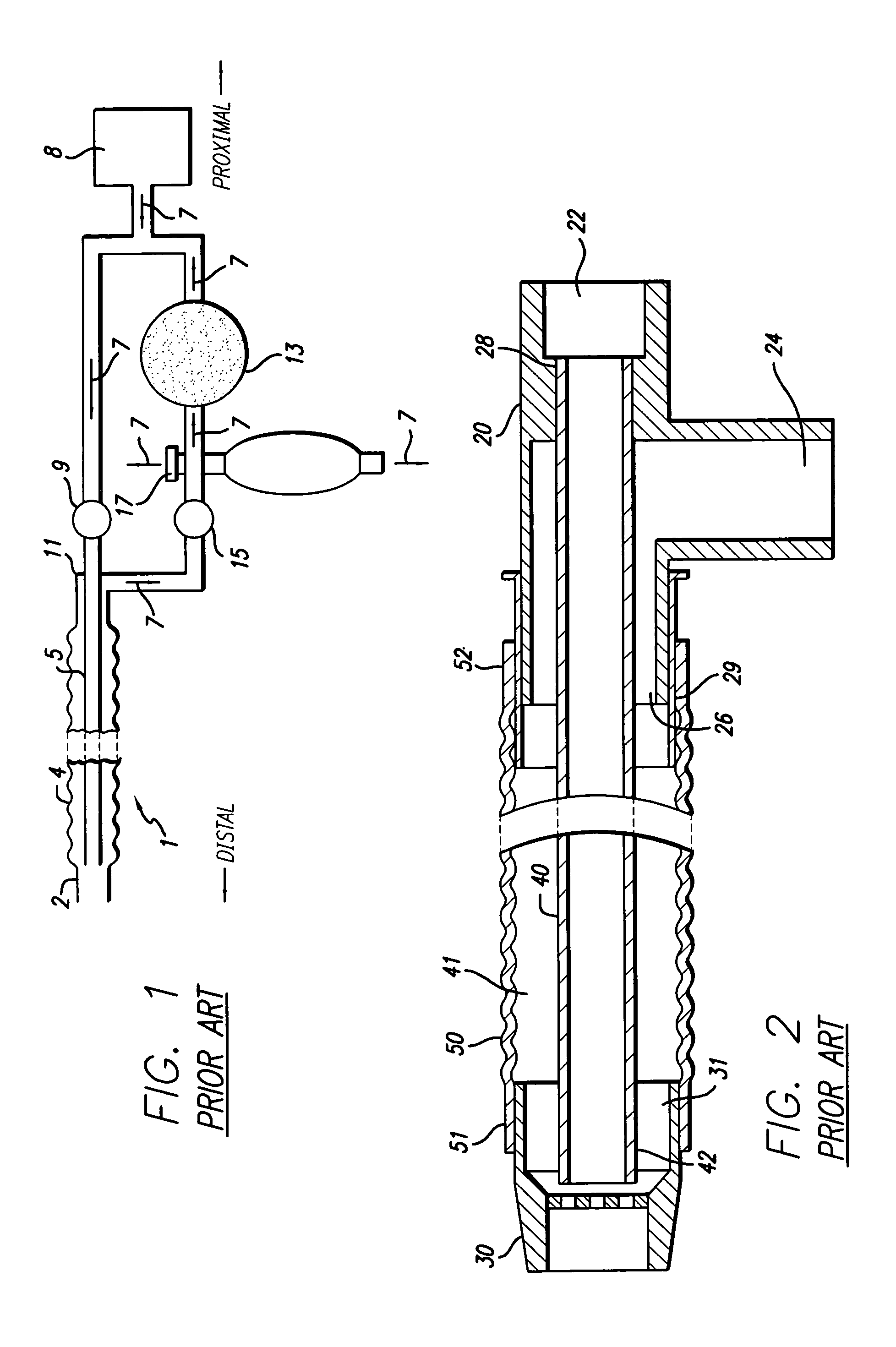
[0056]A brief description of a basic prior art artificial ventilation system and unilimb device will facilitate a description of the present invention. With reference to FIG. 1, a schematic view of a circle circuit artificial ventilation system utilizing a unilimb respiratory (inspiratory and expiratory) gas conduit is illustrated. A unilimb respiratory (or breathing) conduit 1 may be attached at outlet 2 (otherwise referred to as a nozzle or distal terminal) to a patient endotracheal tube or mask. Breathing conduit 1 is formed to include an outer tube 4 and an inner tube 5. Directional arrows 7 show the preferred direction of gas flow through the system; for example, expiratory air is carried away from a patient through the annular spacing between inner tube 5 and outer tube 4. Inspiratory gases are provided to inner tube 5 from a gas source 8, passing through a unidirectional valve 9. Inner tube 5 penetrates the wall of proximal terminal housing 11; housing 11 essentially comprise...


PUM

PropertyMeasurementUnit
lengthaaaaaaaaaa
lengthaaaaaaaaaa
lengthaaaaaaaaaa

Abstract

A multilumen unilimb breathing circuit with a detachable proximal fitting for providing respiratory gases to and receiving expiratory gases from a patient. The circuit has unique fittings for connection to patient devices or assisted ventilation systems and components. Despite many teachings away in the prior art from making breathing circuit tubing detachable from the proximal terminal, the proximal end of the rigid multilumen proximal fitting can be attached and detached by a user at a site of use to a mating multilumen proximal terminal while its distal end can be attached to multiple lumens formed of flexible tubing for carrying gases to and from a patient. The present invention introduces for the first time to the multilumen unilimb circuit art a detachable proximal fitting.

Description

RELATED U.S. APPLICATION DATA[0001]This application is a continuation of U.S. patent application Ser. No. 09 / 930,821, filed Aug. 15, 2001 now abandoned, which is a continuation-in-part of U.S. patent application Ser. No. 09 / 018,540, filed Feb. 4, 1998, now U.S. Pat. No. 5,983,896, issued Nov. 16, 1999, which was a divisional application of U.S. patent application Ser. No. 08 / 751,316, filed Nov. 18, 1996, now U.S. Pat. No. 5,778,872, issued Jul. 14, 1998.FIELD OF THE INVENTION[0002]The present invention relates in one aspect to artificial ventilation methods and systems for administering and exhausting gases to a mammal, including methods and systems for use in anesthesia and administration of oxygen to patients, and more particularly to artificial breathing systems capable of controlling carbon dioxide rebreathing. The present invention relates in another aspect to a unilimb inspiratory and expiratory breathing device for use in a breathing circuit, which has one or more tubular con...

Claims


Application Information

Patent Timeline
Patent Type & Authority Patents(United States)
IPC IPC(8): A61M16/00A61M16/01A61M16/08A61M16/10B01D29/50
CPCA61M16/1055A61M16/08A61M2230/432Y10S128/914Y10S128/912Y10S128/911Y10S55/35A61M2230/435
Inventor FUKUNAGA, ATSUO F.FUKUNAGA, BLANCA M.
Owner AMBU AS
Learn More