Stereoscopic image observing apparatus
- Summary
- Abstract
- Description
- Claims
- Application Information
AI Technical Summary
Problems solved by technology
Method used
Image
Examples
first embodiment
[0036]Hereinbelow, a description is given of embodiments of the present invention with reference to the drawings. First, a stereoscopic image observing apparatus will be described with reference to FIGS. 1 to 7 according to the present invention.
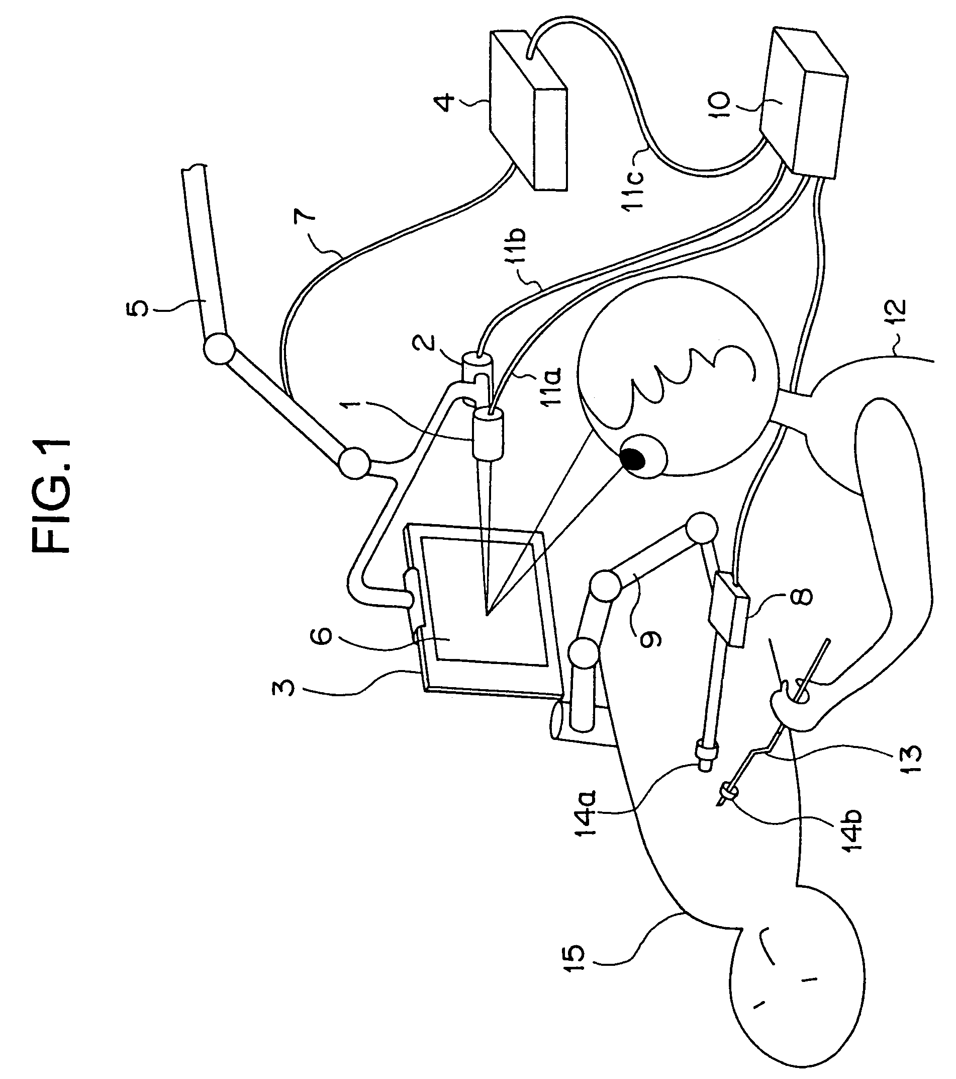
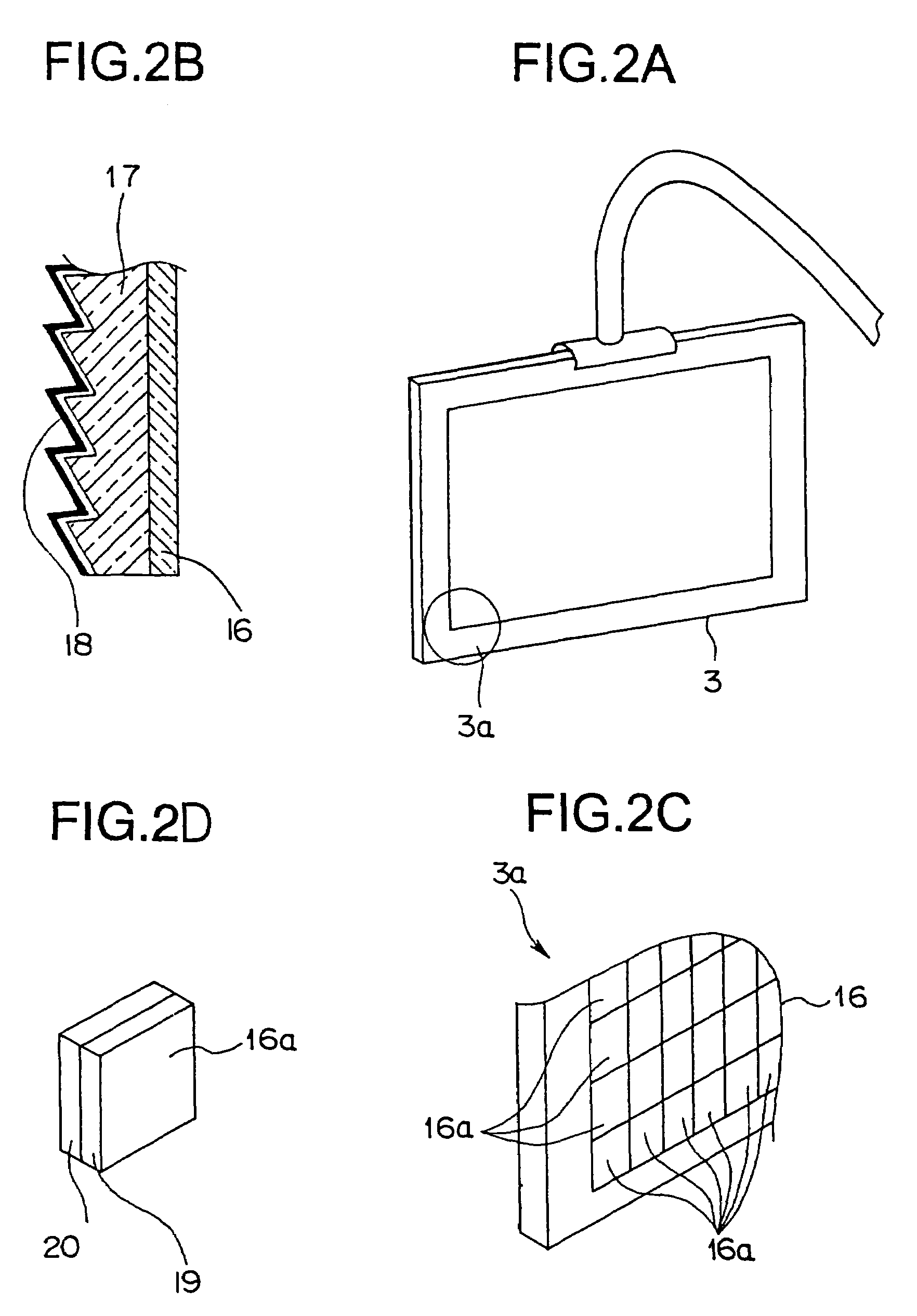
[0037]FIG. 1 is a plan view showing the entire structure of a stereoscopic image observing apparatus according to the first embodiment of the present invention. FIG. 2A is a perspective view showing the structure of an image projecting panel according to the first embodiment. FIG. 2B is a cross-sectional view of the image projecting panel. FIG. 2C is an enlarged perspective view of a portion shown by reference numeral 3a in the image projecting panel shown in FIG. 2A. FIG. 2D is a perspective view showing an optical shift element of the image projecting panel. FIG. 3 is a block diagram showing the structures of an optical shift element driving device and the image projecting panel in the stereoscopic image observing apparatus according to th...
second embodiment
[0084] the sine wave driving signals are applied to the horizontal driving ultrasonic vibrator 33 and the vertical driving ultrasonic vibrator 34, thereby vibrating the light diffusion plate 31 to the Fresnel concave mirror 32. As a result, the image reflected by the light diffusion plate 31 and the Fresnel concave mirror 32 is observed as the stereoscopic image by the operator 12 as the observer, and the roughness as the factor for deteriorating the image quality of the observed image is reduced.
[0085]Next, a description is given of a stereoscopic image observing apparatus according to a modification of the second embodiment with reference to FIG. 11. According to the modification, an image projecting panel 39 is used, instead of the image projecting panel 29 used for the stereoscopic image observing apparatus according to the second embodiment.
[0086]The surface of the light diffusion plate 31 in the image projecting panel 29 has the diffusion surface 37 having the minute uneven po...
third embodiment
[0093] the images for the right and left eyes are projected to the image projecting panel 45 from the right-eye PJ 1 and the left-eye PJ 2. Then, the images for the right and left eyes are enlarged, reflected, and projected by the Fresnel concave mirror 46. The enlarged and projected images for the right and left eyes are diffused and outputted to the both eyes of the operator 12 as the observer with the enlarged pupil diameter upon transmitting the images through the light diffusion plate 47 which is rotated by the diffusion plate rotating mechanism portion 47a.
[0094]The image projecting panel 45 covered with the sterilization drape 49 can be used in the sterilized area such as an operation room, the roughness of the projected image is reduced by the light diffusion plate 47 which is rotated, and the stereoscopic image can be observed with preferable image quality.
[0095]The diffusion plate rotating mechanism portion 47a may be, for example, an air turbine as well as the DC motor, ...
PUM
 Abstract
Description
Claims
Application Information
 - R&D
- Intellectual Property
- Life Sciences
- Materials
- Tech Scout
- Unparalleled Data Quality
- Higher Quality Content
- 60% Fewer Hallucinations
Browse by: Latest US Patents, China's latest patents, Technical Efficacy Thesaurus, Application Domain, Technology Topic, Popular Technical Reports.
© 2025 PatSnap. All rights reserved.Legal|Privacy policy|Modern Slavery Act Transparency Statement|Sitemap|About US| Contact US: help@patsnap.com


