Eureka AIR delivers breakthrough ideas for toughest innovation challenges, trusted by R&D personnel around the world.

Method and system for independently filling multiple canisters from cascaded storage stations

a cascaded storage station and canister technology, applied in the direction of liquid handling, transportation and packaging, packaging goods types, etc., can solve the problems of firefighters waiting for new scba canisters, slow filling process of conventional on-site scba canisters, and limitations of manual processes

Inactive Publication Date: 2008-08-26
SCOTT TECH INC
View PDF10 Cites 117 Cited by
  • Summary
  • Abstract
  • Description
  • Claims
  • Application Information

AI Technical Summary

Benefits of technology

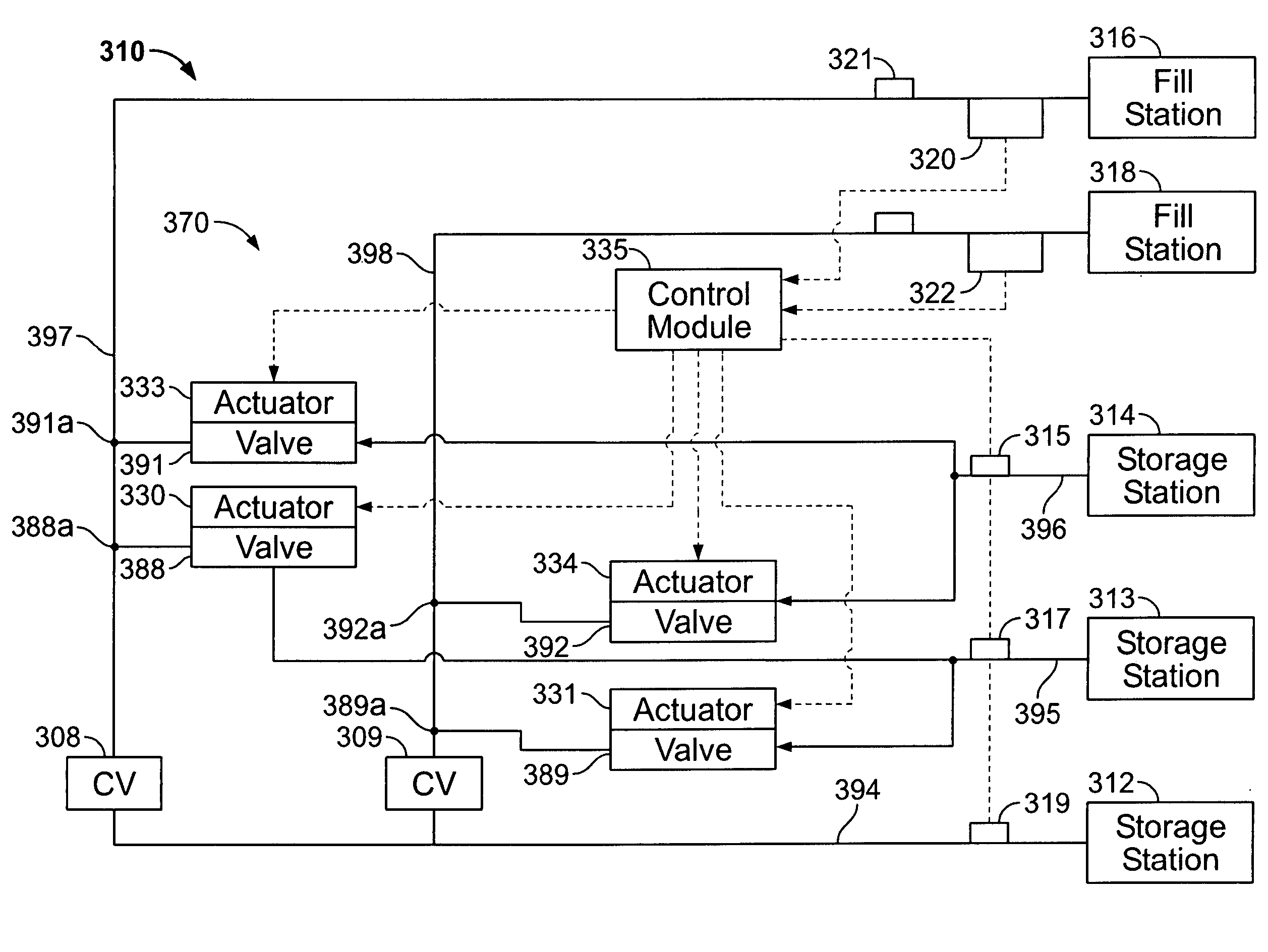
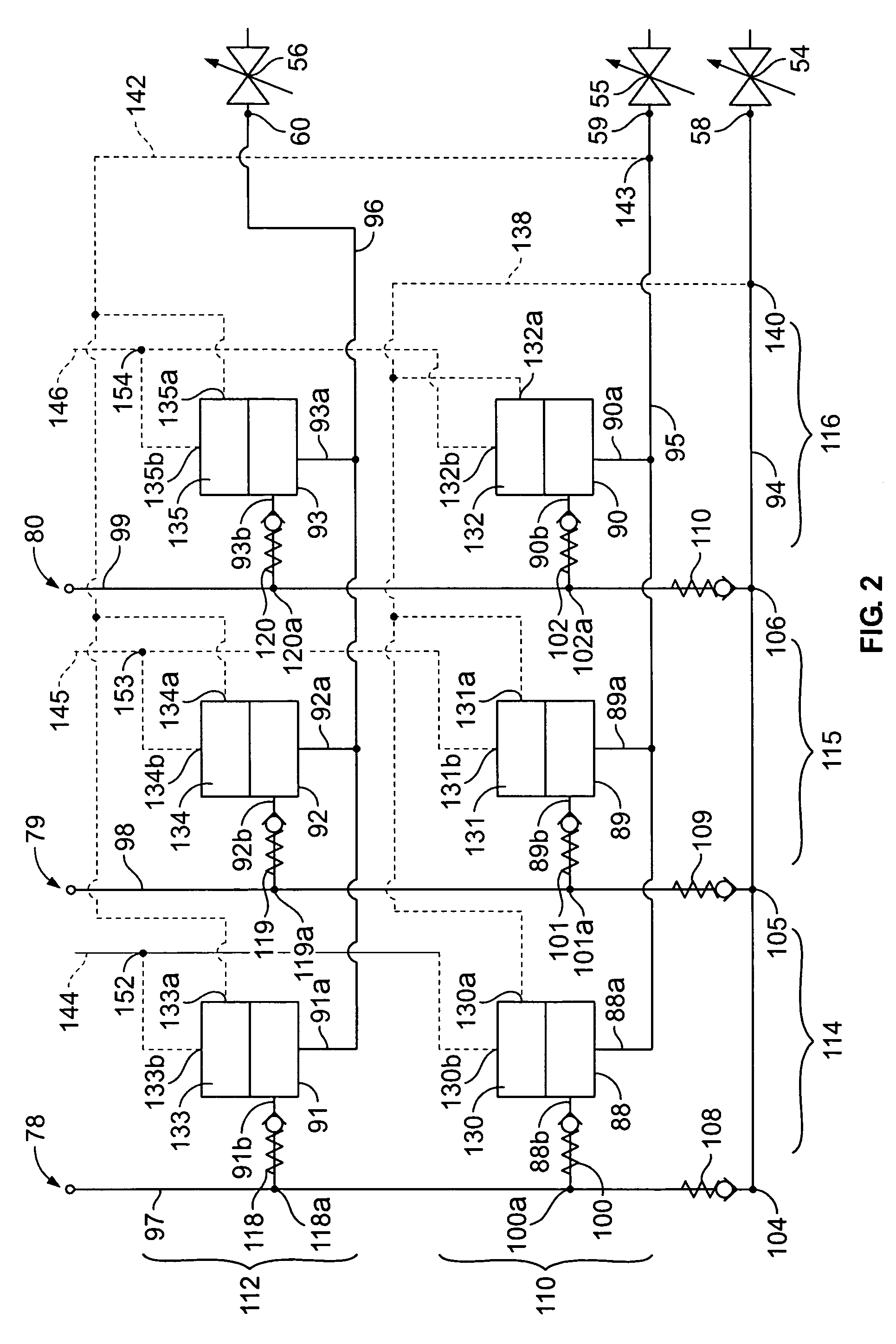
[0011]A canister filling system is provided for independently and automatically filling multiple canisters from a common set of storage stations arranged in a prioritized cascaded manner. The system includes at least first and second fill stations provided to receive and independently fill canisters with pressurized gas. At least first and second storage stations are configured to discharge gas at corresponding first and second charge pressures, respectively. A supply-chain independently joins each of the first and second fill stations to both of the first and second storage stations. First and second valve assemblies are provided in the supply-chain to monitor, independent of one another, the canister pressures at the corresponding first and second fill stations. The canister pressures represent the individual pressure within corresponding canisters. The first and second valve assemblies automatically open and close to permit and prevent discharge of gas from the first and second storage stations, independent of one another, to automatically prioritize and switch between the first and second storage stations based on the canister pressures.
[0013]In accordance with another embodiment, a method is provided for independently filling multiple canisters from a common set of cascaded storage stations. The method includes attaching canisters to first and second fill stations, where the first and second fill stations are joined along separate lines to a common set of prioritized cascaded storage stations. The cascaded storage stations include first and second storage stations configured to discharge gas at select different first and second charge pressures. The method further includes monitoring the canister pressure at each of the individual canisters at the first and second fill stations, independent of one another, and separately comparing the canister pressure from each of the canisters to the first and second charge pressures. The method further includes automatically opening and closing valves to permit and prevent discharge of gas from the first and second storage stations to the first and second fill stations, thereby prioritizing and switching between the first and second storage stations based on the corresponding canister pressures.

Problems solved by technology

However, the conventional manual process has experienced several limitations.
The conventional on-site SCBA canister filling process is slow as it typically requires each a series of valves to be opened and closed manually in order to complete the fill process, which may result in firefighters waiting for new SCBA canisters to be filled without being able to assist in fighting a fire.

Method used


Image

  • Method and system for independently filling multiple canisters from cascaded storage stations
  • Method and system for independently filling multiple canisters from cascaded storage stations
  • Method and system for independently filling multiple canisters from cascaded storage stations

Examples


Embodiment Construction

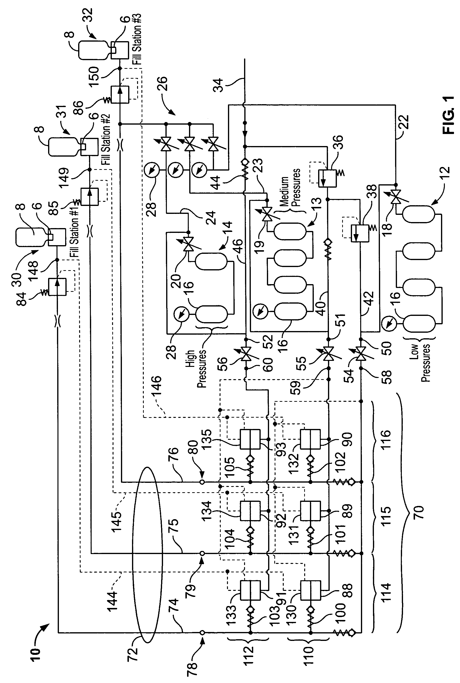
[0019]FIG. 1 illustrates a flow diagram of a canister filling system 10 that is provided in accordance with an embodiment of the present invention. By way of example, canisters 8 may represent SCBA canisters utilized by firefighters. The canisters 8 are attached and decoupled to / from fill stations 30-32 by couplings 6 before and after a complete filling operation. The system 10 includes fill stations 30-32 that are independently attached to a common set of prioritized storage stations, namely a first or primary pressure storage station 12, a second or secondary storage station 13 and a third or tertiary pressure storage station 14. The fill stations 30-32 are configured to receive and independently fill canister 8 with pressurized gas (e.g. anesthesia, oxygen, air, CNG, nitrogen, carbon dioxide and the like). The storage stations 12-14 are joined in a prioritized cascaded manner and configured to discharge gas at corresponding charge pressures.

[0020]The storage stations 12-14 may in...


PUM

PropertyMeasurementUnit
pressureaaaaaaaaaa
pressureaaaaaaaaaa
pressure differentialaaaaaaaaaa

Abstract

A canister filling system is provided for independently filling multiple canisters from a common set of storage stations prioritized in a cascaded manner. The system includes first and second fill stations configured to receive and independently fill canisters with pressurized gas. First and second storage stations store gas at corresponding first and second charge pressures, respectively. A supply-chain joins each of the first and second fill stations to both of the first and second storage stations. First and second valve assemblies are provided in the supply-chain to monitor, independent of one another, the canister pressures at the corresponding first and second fill stations. The canister pressures represent the pressure within corresponding canisters. The first and second valve assemblies automatically open and close to permit and prevent discharge of gas from the first and second storage stations, independent of one another, to automatically switch between the first and second storage stations based on the canister pressures. In one embodiment, the valve assembly includes a combination of sequence valves and check valves. Alternatively, the valve assembly may be controlled by electronic sensors and electronic solenoids. The electronic sensors detect the canister pressures and the charge pressures at the storage stations. The electronic solenoids open and close the valves based on the sensed canister pressures.

Description

BACKGROUND OF THE INVENTION[0001]The invention relates generally to methods and systems for, independently and automatically, filling canisters from a common set of pressurized storage stations arranged in a priority cascaded manner.[0002]Numerous types of canisters exist for storing pressurized gas, such as anesthesia, air, oxygen, carbon dioxide, nitrogen, compressed natural gas (CNG) and the like. One example of a canister is a self-contained breathing apparatus (SCBA) which may be used in various applications, such as by firefighters, in medical applications, in recreational underwater diving applications and the like. Various systems exist for filling the canisters with the appropriate type and amount / pressure of gas.[0003]Heretofore, a manual filling system has been utilized in firefighting applications to refill firefighter SCBA canisters on-site at a fire, emergency or other catastrophic event. In firefighter applications, a fire truck or other vehicle carries recharging sto...

Claims


Application Information

Patent Timeline
Patent Type & Authority Patents(United States)
IPC IPC(8): B65B1/04
CPCF17C6/00F17C2250/0626F17C2201/0109F17C2205/0326F17C2205/0329F17C2205/0335F17C2205/0338F17C2221/011F17C2221/013F17C2221/014F17C2221/031F17C2221/033F17C2223/0123F17C2227/0157F17C2250/032F17C2250/043F17C2227/043
Inventor PLUMMER, DARRILL LEEPOSOD, GAYLORD KERN
Owner SCOTT TECH INC
Why Eureka
Eureka Blog
Learn More