
Air bag apparatus

a technology of airbags and air bags, which is applied in the direction of vehicular safety arrangements, pedestrian/occupant safety arrangements, vehicle components, etc., can solve the problems of inability to stably protect passengers, small amount of recessing of airbags, and limited position of mounting the airbag apparatus to the vehicle, so as to facilitate the manufacture of airbags

Inactive Publication Date: 2008-07-29
TOYODA GOSEI CO LTD
View PDF31 Cites 23 Cited by
  • Summary
  • Abstract
  • Description
  • Claims
  • Application Information

AI Technical Summary

Benefits of technology

This design enhances passenger protection by maintaining consistent restraint across varying passenger configurations and reduces the initial expanding speed, while allowing for flexible mounting and effective obstacle avoidance.

Problems solved by technology

Further, when the head portion of the passenger interferes with a portion thereof remote from the center axis of the through hole, an amount of recessing the air bag is small.
Therefore, according to the air bag apparatus of the related art, the function of constraining the passenger is dispersed by a physical constitution and an attitude of the passenger and there is a concern of being unable to stably protect the passenger.
According to the air bag apparatus disclosed in JP-A-11-170955, a portion of the air bag needs to press to an instrument panel or a windshield by the inner bag and a position of mounting the air bag apparatus to the vehicle is limited.
However, according to the air bag apparatus of the related art, the expanded portion for protecting the head portion of the passenger is supported by the supporting member, an expanded portion for protecting the chest and the belly portion of the passenger is not supported by the supporting member, depending on elastic performance of the supporting member, by presence or absence of the supporting member, the chest and belly portion of the passenger is constrained by the protecting expanded portion with excellent positioning performance, however, there is a concern that the head portion of the passenger is not constrained by the protecting expanding portion of the head portion.

Method used


Image

  • Air bag apparatus
  • Air bag apparatus
  • Air bag apparatus

Examples


first embodiment

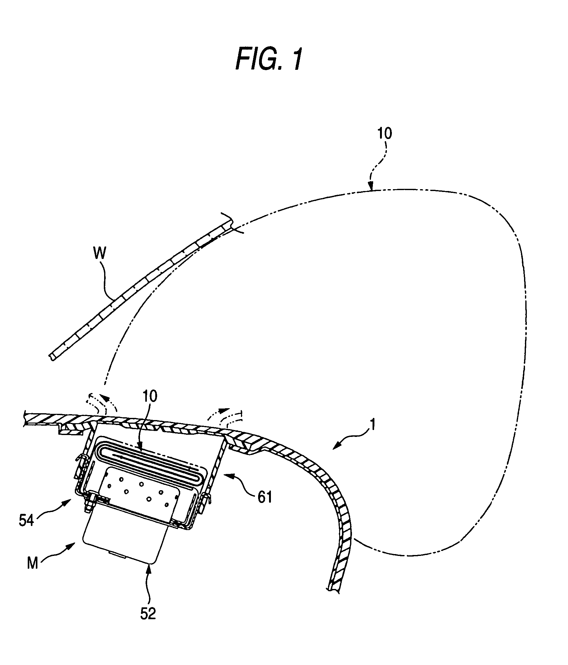
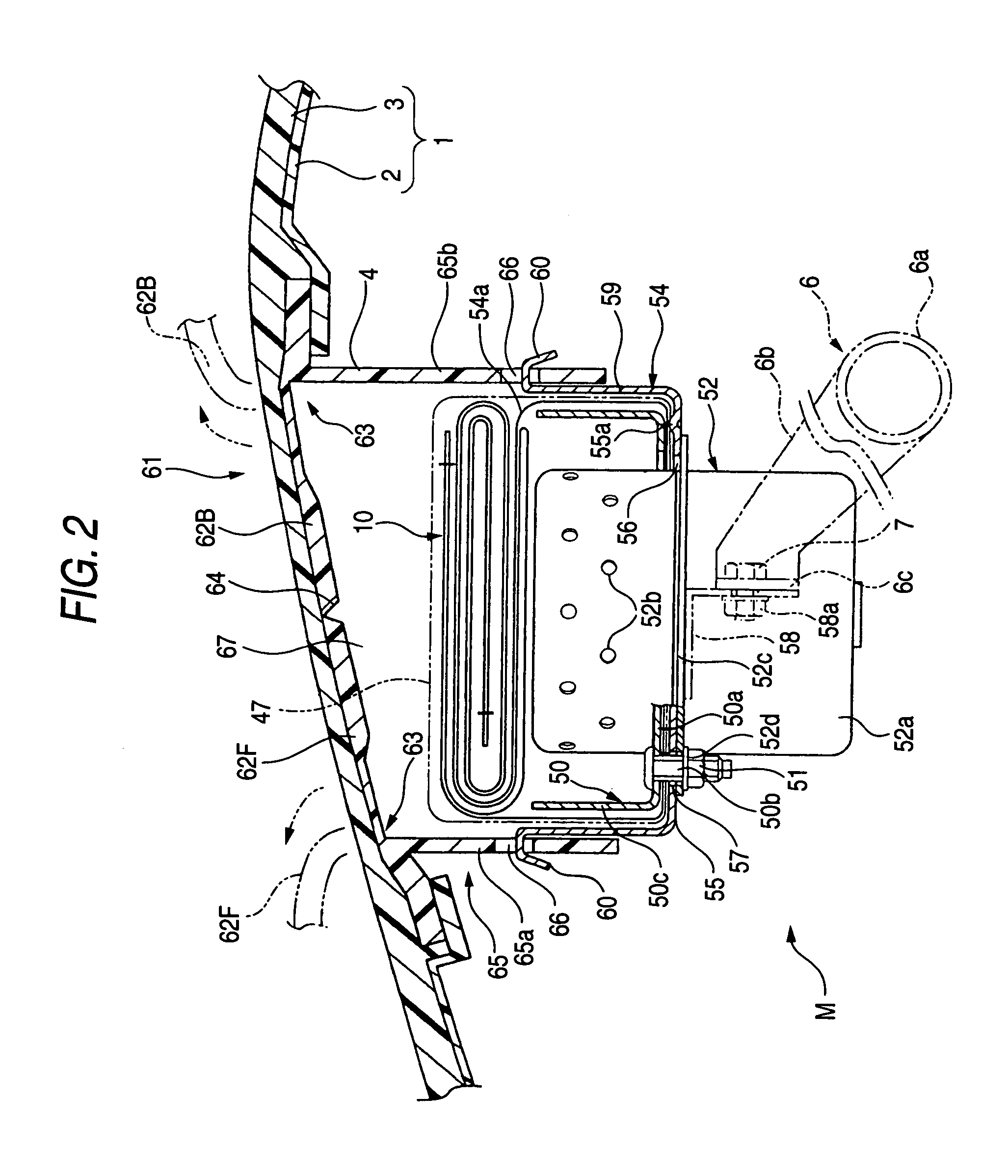
[0125]First, an explanation will be given of an air bag apparatus M for a passenger seat constituting a first embodiment of the invention. As shown by FIGS. 1 and 2, an air bag apparatus 1 is of a top mount type arranged at an inner portion on a side of an upper face of a surface of an instrument panel (inpane) 1. The air bag apparatus M is constituted by including a folded air bag 10, an inflator 52 for supplying an expanding gas to the air bag 10, a case 54 for containing to hold the air bag 10 and the inflator 52, a retainer 50 for attaching the air bag 10 to the case 54, and an air bag cover 61 for covering the folded air bag 10.

[0126]As shown by FIGS. 1 and 2, an air bag cover 61 is integrally formed with the instrument panel 1 in the case of the embodiment. The instrument panel 1 is constituted by including a base portion 2 on a rear face side comprising a hard synthetic resin of polypropylene or the like, and a cover layer 3 having a foamed layer of foamed polyurethane or the...

second embodiment

[0157]An explanation will be given of a second embodiment of an air bag apparatus of the invention.

[0158]As shown by FIG. 14, a passenger seat 215 constituted by a seating portion 213 and a backrest portion is arranged at a floor face 212 of a vehicle 211 such that a position in a front and rear direction in a vehicle advancing direction can be adjusted. An instrument panel 216 is arranged in front of the passenger seat 215. Inside of the instrument panel 216 is contained with an air bag apparatus 221 having an air bag 223 expanded to develop between an upper face of the instrument panel 216, an inner face of a windshield 217 disposed on an upper side of the instrument panel 216 and a passenger seated on the passenger seat 215.

[0159]The air bag apparatus 221 is constituted by a containing case 222 contained to fix to inside of the instrument panel 216, the air bag 223 folded to contain at inside of the containing case 222, and an inflator 224 arranged to penetrate a bottom portion o...

third embodiment

[0181]Next, a third embodiment of the invention will be explained.

[0182]FIG. 21 is a front view of developing respective sheets and the like constituting the air bag 223, FIG. 22 is a plane view of an initial state of expanding the air bag 223, and FIG. 23 is an enlarged sectional view passing the inflator 224 and a head and tail integrated portion 244 of FIG. 22.

[0183]According to the embodiment, the air bag 223 is made to expand to develop in the left and right direction widely in the width direction by deflecting the gas injected from the injecting port 224a of the inflator 224 into the front expanded portion 229 in the left and right direction. In fabricating the air bag 223, as shown by FIG. 21, an outer peripheral edge E9 of a reinforcing cloth 242 is seamed to a side of an inner face of the outer sheet 225 by sewing string. Similar thereto, also an outer peripheral edge E9 of the reinforcing cloth 243 is seamed to an inner face of the inner sheet 227 by sewing string. Next, a...


PUM


Abstract

An air bag apparatus having a constitution of developing an air bag folded to contain in a case to a rear side of a vehicle by making an expanding gas flow from a gas flow inlet in expanding to develop the air bag. The air bag is arranged with a through hole. The air bag is constituted by a ring-like member arranged with a lower expanded portion arranged with a gas flow inlet, an upper expanded portion arranged to an upper side of the lower expanded portion to communicate with a front side of the lower expanded portion, and a rear expanded portion arranged to connect to a rear part of the lower expanded portion and a rear part of the upper expanded portion at a surrounding of the through hole. The air bag is constituted to finish to expand by closing the through hole.

Description

[0001]This application is based on Japanese Patent Applications No. 2003-196831, 2003-323108, 2003-323117, 2003-323122 and 2003-323128, which are incorporated herein by reference.BACKGROUND OF THE INVENTION[0002]1. Field of the Invention[0003]The present invention relates to an air bag apparatus installed at an instrument panel and constituted to develop an air bag folded to contain at inside of the case.[0004]2. Description of the Related Art[0005]In a related art, according to an air bag apparatus having the above-described constitution, an air bag is provided with a through hole penetrated in a left and right direction (refer to, for example, JP-A-6-344844).[0006]However, the air bag apparatus of the related art is constituted such that the through hole provided at the air bag is not closed even in finishing to expand the air bag. That is, according to the air bag of the related art, a dispersion is brought about in a function of constraining the passenger at a portion thereof on...

Claims


Application Information

Patent Timeline
Patent Type & Authority Patents(United States)
IPC IPC(8): B60R21/16B60R21/205B60R21/2165B60R21/233B60R21/2338B60R21/237B60R21/239
CPCB60R21/205B60R21/233B60R21/237B60R21/2338B60R21/2165B60R2021/23386B60R21/239B60R2021/23324
Inventor BITO, KAZUAKIHAYASHI, KAZUTOSHI
Owner TOYODA GOSEI CO LTD
Learn More