Lace securing apparatus

a technology for securing devices and laces, applied in the direction of fastenings, press-button fasteners, uppers, etc., can solve the problems of easy untying of laces, children often over-looking this danger, and it is difficult or impossible to tie or retie laces. , to achieve the effect of convenient us

Inactive Publication Date: 2008-07-29
PERLER JANELLE
View PDF14 Cites 37 Cited by
  • Summary
  • Abstract
  • Description
  • Claims
  • Application Information

AI Technical Summary

Benefits of technology

[0021]An object of the present invention is to disclose an apparatus that is easy to use so that young children or disabled adults can use the present invention.

Problems solved by technology

The problem of laces becoming untied is typical for all shoes containing laces.
For most adults this is an annoyance that is easily overcome by the re-tying of the lace.
However, children often over look this danger because they lack life experience or the untied lace goes unnoticed.
In addition, adults may have disabilities that make it impossible or difficult to tie or retie their laces.
In addition, these methods do not offer interchangeability in design that would make them universally appropriate for securing laces.
An example of how these prior inventions are limited are that they require a more complicated securing process and they have only one outwardly appearance that may not be desirable or appropriate for the laces that are being secured.
None of the prior art couple the securing of laces with added security features such as sounds alarms or locating signals to find wayward users.
None of the prior art provides a means for presenting interchangeable images onto shoes.
Nothing in the prior art references disclose an apparatus or method that utilizes a combination of these elements to facilitate the securing of tied laces.

Method used


Image

  • Lace securing apparatus
  • Lace securing apparatus
  • Lace securing apparatus

Examples


Embodiment Construction

[0050]Shown throughout the figures, the present invention is directed towards a lace gripper. Like element references are used through the various figures.

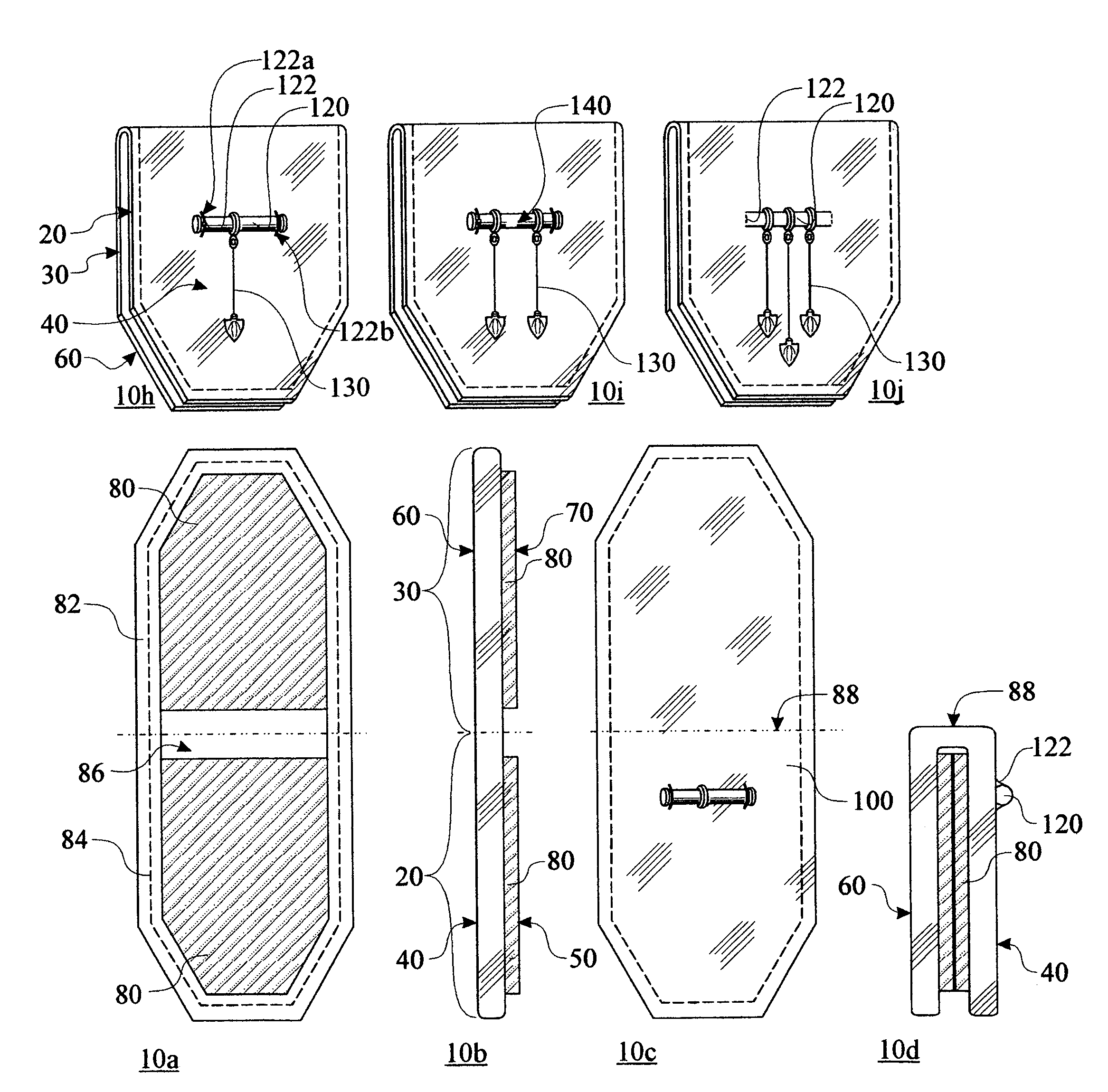
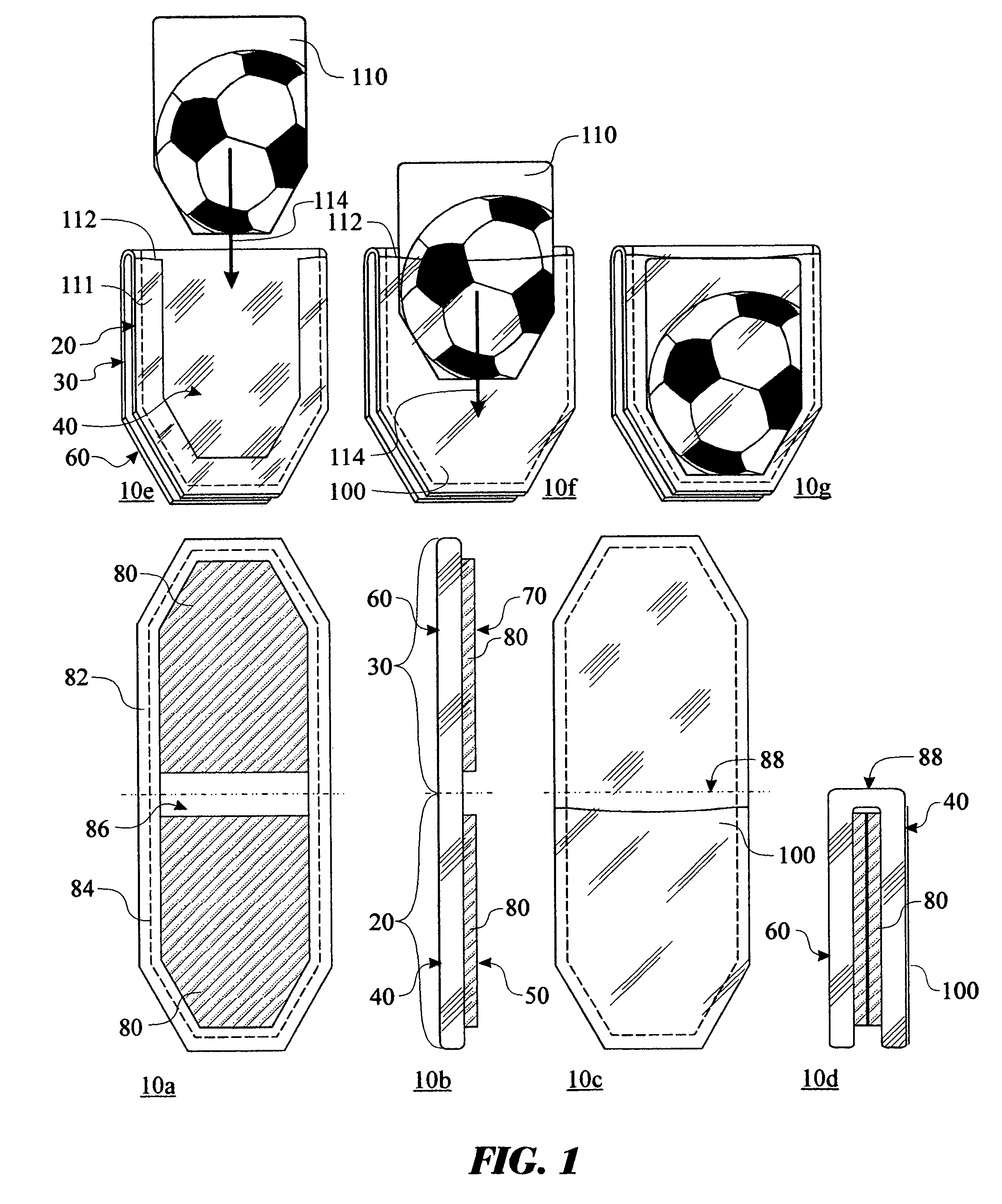
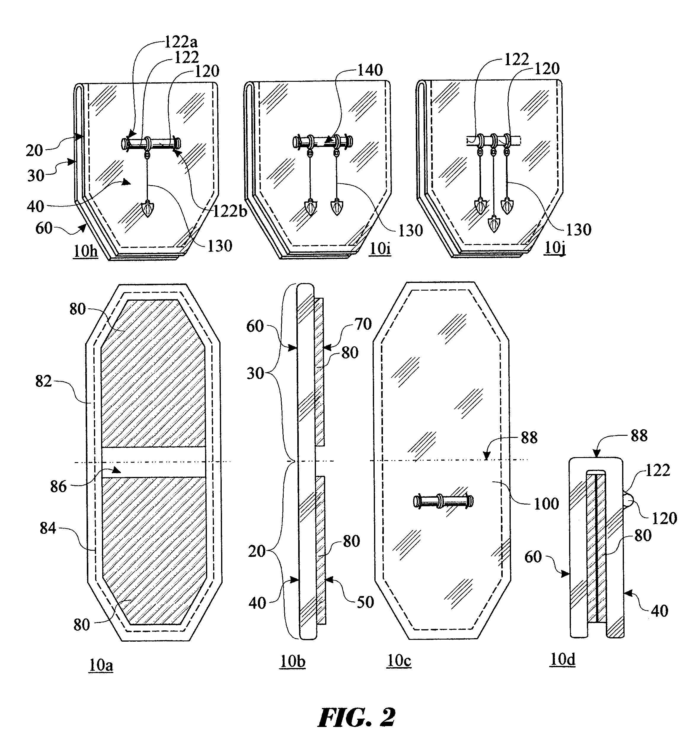
[0051]FIG. 1 illustrates a lace gripper 10 (shown as 10A-10p herein), said lace gripper comprising a lace gripper upper body 20 and a lace gripper lower body 30. Said lace gripper upper body 20 has an upper body outer surface 40 and an upper body joining surface 50. Said lace gripper upper body 20 is the portion of said lace gripper 10 that is visible when used. Said lace gripper lower body 30 has a lower body outer surface 60 and a lower body joining surface 70. Said lace gripper lower body 30 is the portion of said lace gripper 10 that is not visible when used, placed behind said lace gripper upper body 20. Said upper body joining surface 50 and said lower body joining surface 70 further comprise an interlocking means 80 used as a means for securing said upper body joining surface 50 and said lower body joining surface 70, formi...


PUM


Abstract

The invention is for a lace gripper comprising an upper body and a lower body that may be joined together whereby a tied lace is secured between the two bodies. Preferable the upper body is designed to receive inserts, charms, lights, recording devices, alarm and locating audible signals and locating devices, to allow the user to customize the lace gripper to their personal preference. The lace gripper can additionally be utilized to maintain a memo and would be secured to an object of daily use, such as a key ring or purse.

Description

BACKGROUND OF THE INVENTION[0001]1. Field of the Invention[0002]The invention relates generally to an apparatus for securing laces of a shoe. The apparatus comprises a folded piece of material that can wrap around adjoined laces to ensure that said laces stay adjoined.[0003]2. Description of the Prior Art[0004]There currently exist several methods for securing adjoined, or tied, laces. Often these methods involve the use of fine motor skills to engage the laces. The problem of laces becoming untied is typical for all shoes containing laces. For most adults this is an annoyance that is easily overcome by the re-tying of the lace. Most adults have life experience that teaches them to retie their laces so that a dangerous accident can be avoided from the tripping over of untied laces. However, children often over look this danger because they lack life experience or the untied lace goes unnoticed. In addition, there are several occasions where adults will also notice that a lace is unt...

Claims


Application Information

Patent Timeline
Patent Type & Authority Patents(United States)
IPC IPC(8): A43C7/00
CPCA43B3/0078A43B23/24A43C7/005A43C11/24Y10T24/3708Y10T24/3705Y10T24/3711Y10T24/27
Inventor PERLER, JANELLE
Owner PERLER JANELLE
Why Eureka
Try Eureka