
Method and device for aligning a receiving envelope in a mail inserter

a technology of receiving envelope and mail inserter, which is applied in the field of mail inserter, can solve the problem that the clearance of the receiving envelope on the other side may not be achievabl

Active Publication Date: 2008-07-15
PITNEY BOWES INC
View PDF9 Cites 24 Cited by
  • Summary
  • Abstract
  • Description
  • Claims
  • Application Information

AI Technical Summary

Benefits of technology

"The patent describes a mechanism for inserting material into envelopes. It uses optical sensing to determine the position of the material and the envelope, and adjusts for any errors in the clearance between the two. This ensures that the material is inserted properly and can be seen without any issues. The mechanism is controlled by a stepper motor, which moves the envelope perpendicular to its edges to adjust the clearance. The technical effect of this invention is to improve the accuracy and efficiency of inserting material into envelopes."

Problems solved by technology

However, misalignment due to various factors may occur such that the required end clearance on one side of the receiving envelope may not be achievable.

Method used


Image

  • Method and device for aligning a receiving envelope in a mail inserter
  • Method and device for aligning a receiving envelope in a mail inserter
  • Method and device for aligning a receiving envelope in a mail inserter

Examples


Embodiment Construction

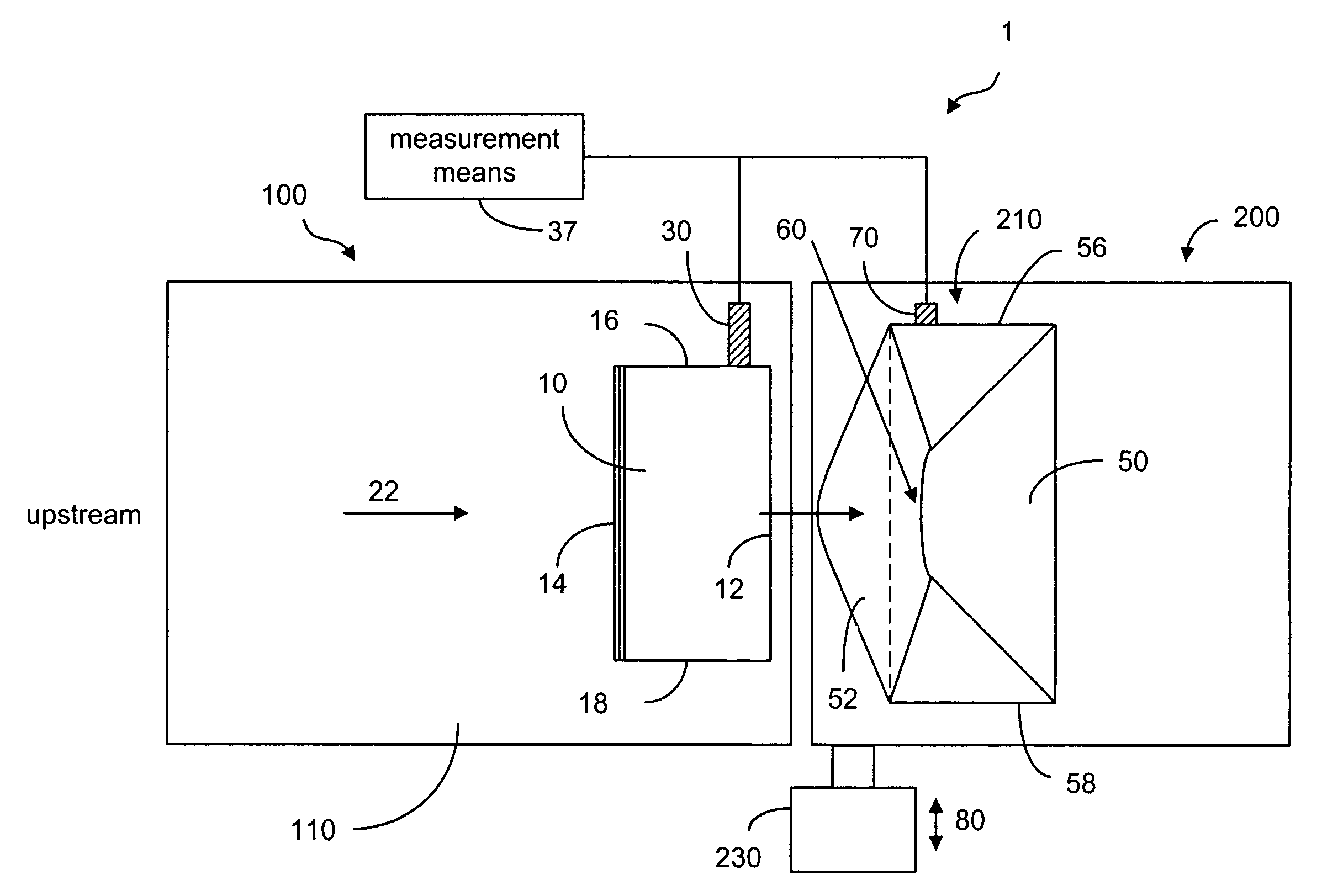
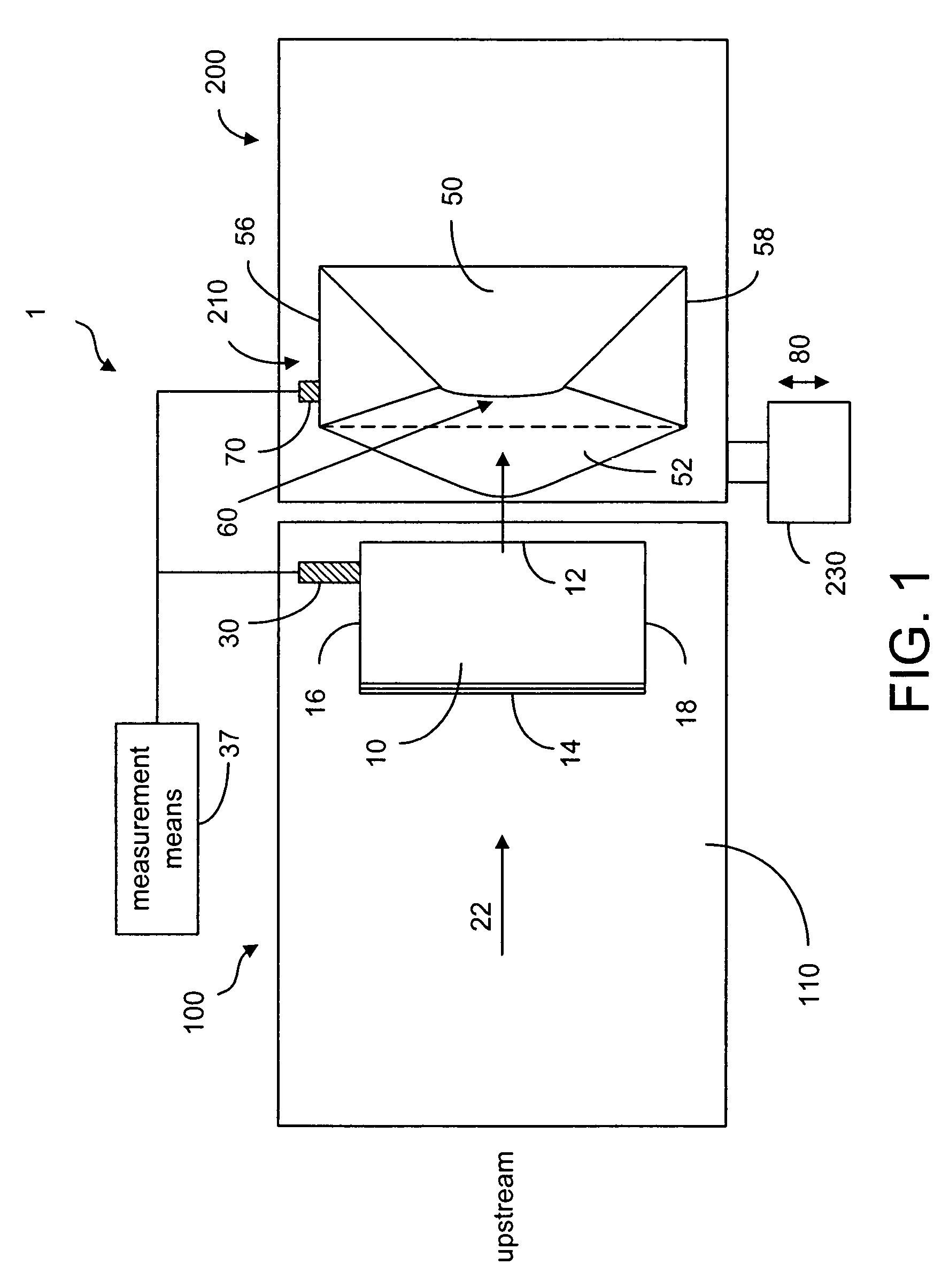
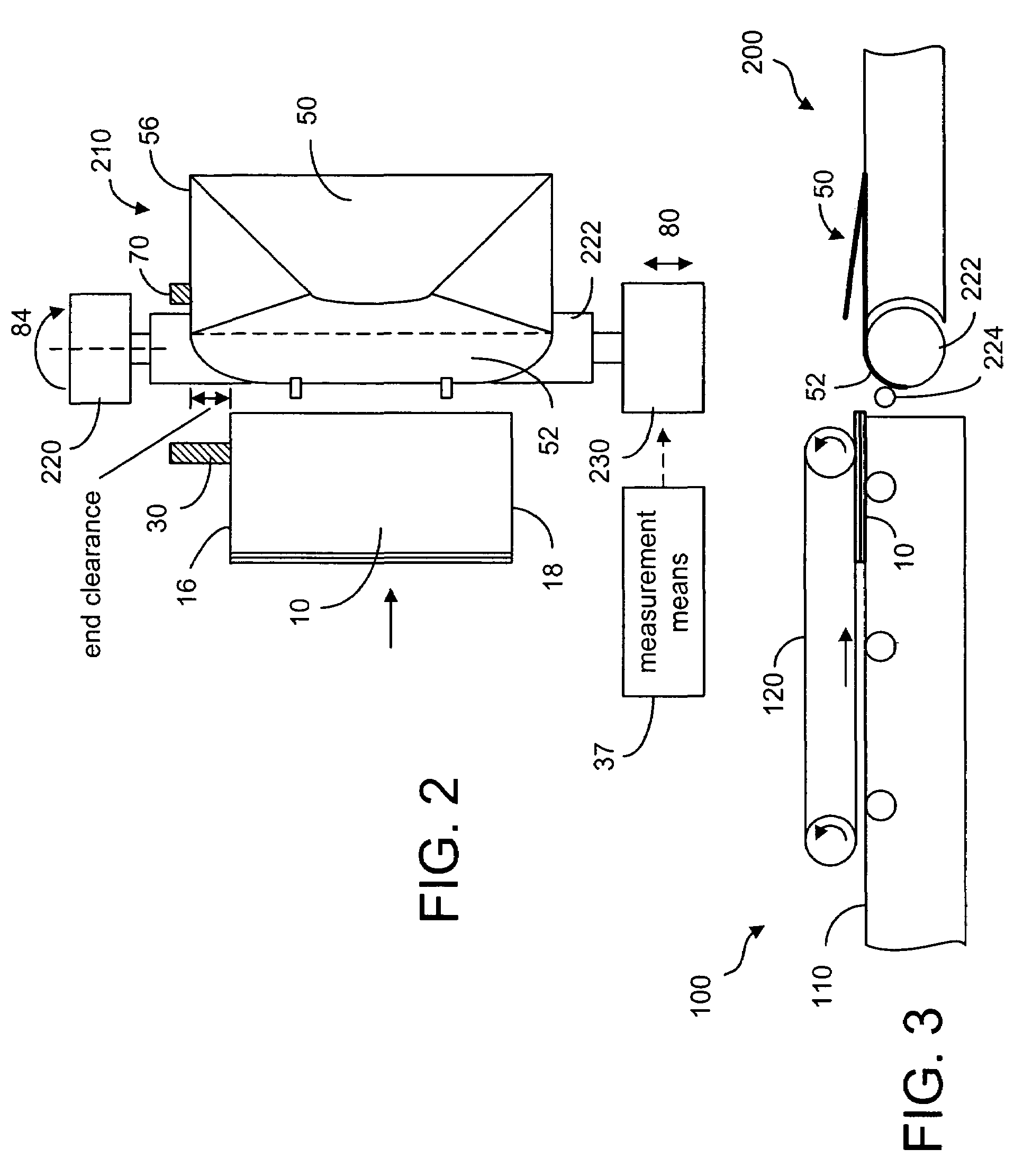
[0011]FIG. 1 is a schematic representation of a mail inserter section in a mailing machine where a pack of insert material is inserted into an envelope. As shown in FIG. 1, the mail inserter section 1 has a feeder 100 for feeding a pack of insert material 10 from an upstream direction to an insertion station 200. In the insertion station 200, an envelope 50 is placed in an insertion area with the flap 52 of the envelope 50 opened to receive the insert material 10. As shown, the insert 10 has a leading edge 12 and a trailing edge 14 defined by the feeding direction 22. The insert material has a first side edge 16 and a second side edge 18, defining the width of the insert material 10. The envelope 50 has a first side edge 56 and a second side edge 58, defining the width of the envelope. In order to ensure that the insert material 10 is properly inserted into the receiving envelope 50, the width of the envelope must be greater than the width of the insert material by a certain amount ...


PUM

PropertyMeasurementUnit
thickaaaaaaaaaa
widthaaaaaaaaaa
distanceaaaaaaaaaa

Abstract

In a mail inserter having an envelope movement mechanism to move an envelope into an insertion station and a feeder to move a pack of insert material into an insertion position so that the insert material can be inserted into the envelope, a linear array of optical sensing elements is used to determine the position of one edge of the insert material and another linear array of optical sensing elements is used to determine the position of one edge of the receiving envelope in order to make sure that there is sufficient end clearance between the insert material and the receiving envelope. A stepper motor is used to adjust the envelope position, if the end clearance is outside a predetermined range.

Description

TECHNICAL FIELD[0001]The present invention relates generally to a mail inserter and, more particularly, to the adjustment of a receiving envelope in the insertion station relative to the insert material.BACKGROUND OF THE INVENTION[0002]A typical mailing machine has a mail inserter section where a pack of insert material is inserted into an envelope. The mailing machine may have an accumulation section where a plurality of insert documents are fed and accumulated into a stack. The accumulated documents may be folded. The mailing machine may also have a printing section for printing the insert documents or the envelopes. In order to ensure that a pack of insert material is properly inserted into a receiving envelope, the width of the envelope must be greater than the width of the pack by a certain amount. The minimum difference in width allowed on each side of the envelope is referred to as the required “end clearance”. The required end clearance depends on the thickness of the pack t...

Claims


Application Information

Patent Timeline
Patent Type & Authority Patents(United States)
IPC IPC(8): B65B43/26
CPCB43M3/045
Inventor FAIRWEATHER, JAMES A.DOUTNEY, GEORGE J.ALLEN, ROBERT J.LYGA, THOMAS M.GOSLICKI, JR., DANIEL P.
Owner PITNEY BOWES INC
Learn More