
Phase diversity ranging sensor

a technology of phase diversity and distance measurement, applied in the field of distance determination, can solve the problems of difficult to determine the distance (range) to an object in space, existing systems may be unduly complex or cumbersome, and achieve the effect of efficient and accurate distance determination

Inactive Publication Date: 2008-07-08
THE BOEING CO
View PDF6 Cites 16 Cited by
  • Summary
  • Abstract
  • Description
  • Claims
  • Application Information

AI Technical Summary

Benefits of technology

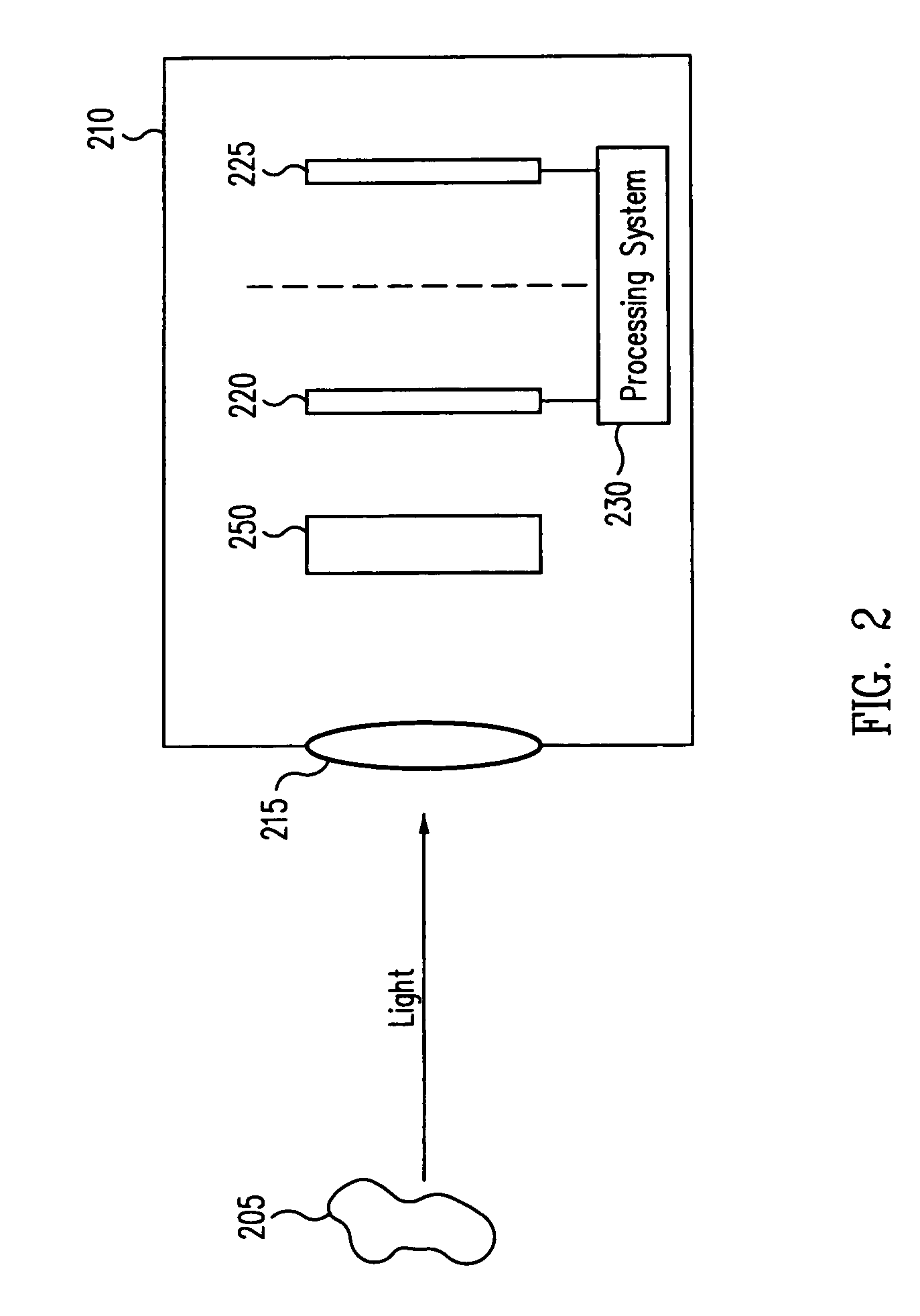
[0007]Systems and techniques provided herein allow for efficient and accurate distance determination by introducing one or more aberrating elements into the optical path from an object. Image information is then obtained at different focus conditions, and processed to determine the distance. The systems and techniques herein are particularly useful for space applications in which the distance to an object is large enough that its size and / or features cannot be resolved sufficiently to determine that distance.

Problems solved by technology

Determining a distance to a particular object may be difficult in some circumstances.
For example, it may be difficult to determine the distance (range) to an object in space.
However, existing systems may be unduly complex or cumbersome.

Method used


Image

  • Phase diversity ranging sensor
  • Phase diversity ranging sensor
  • Phase diversity ranging sensor

Examples


Embodiment Construction

[0028]Systems and techniques provided herein allow for accurate measurement of distances in the meter to kilometer range. The systems may be incorporated into existing camera systems, and require significantly less power than laser and radar ranging systems. Thus, they may be beneficial for applications in which power is limited, as well as applications in which size is important. Additionally, because of their relative simplicity, the techniques may be implemented at low cost.

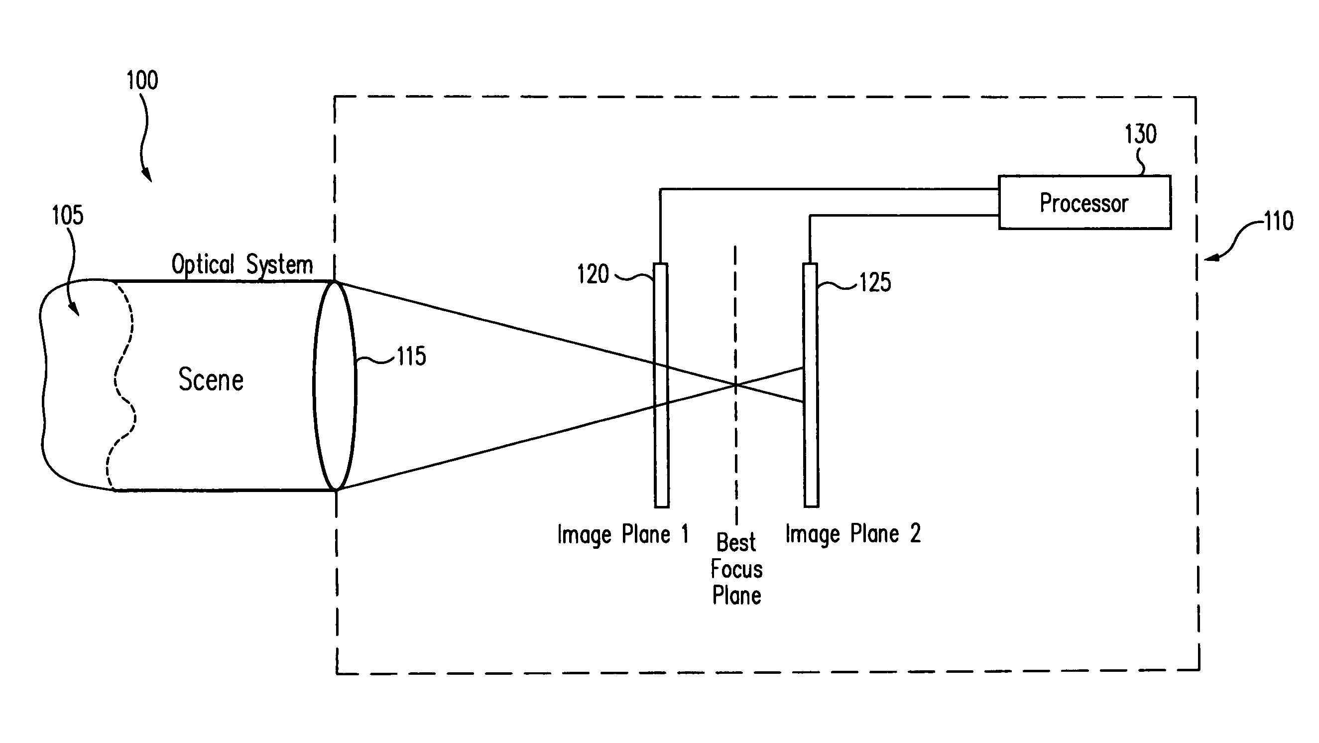
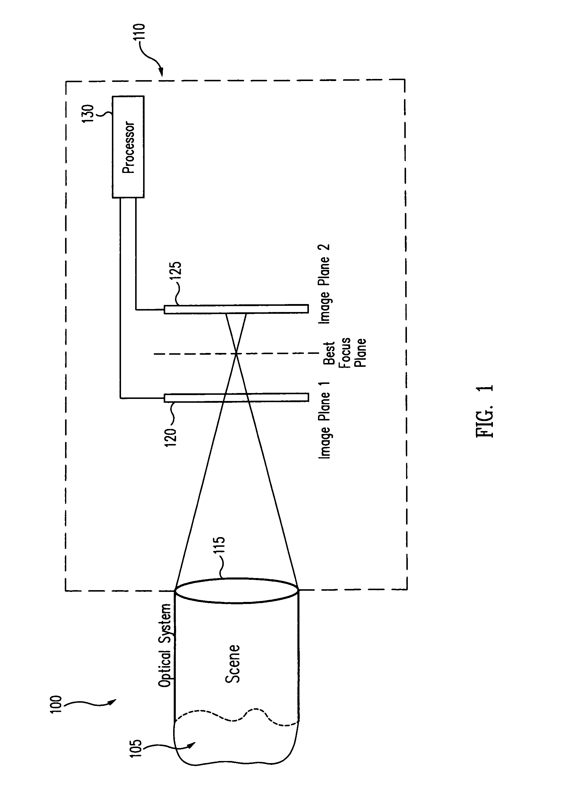
[0029]Embodiments of the current invention use phase diversity to determine the distance to an object of interest. In some prior art systems, phase diversity imaging is used to counter-act the affect of aberration on image quality. FIG. 1 illustrates a simple system 100 for image processing using phase diversity.

[0030]An object 105 is at a distance D from an optical system 110. Note that FIG. 1 is not shown to scale; for example, D is much larger than the relative separations of elements in optical system 110....


PUM


Abstract

A system to determine the distance to an object includes one or more aberrating elements to introduce aberration into light from the object. Image data is obtained at two different focus conditions, and used to determine the object distance.

Description

BACKGROUND[0001]1. Field of Invention[0002]This invention generally relates to distance determination, particularly distance determination for space applications.[0003]2. Related Art[0004]Determining a distance to a particular object may be difficult in some circumstances. For example, it may be difficult to determine the distance (range) to an object in space. Distances of interest in space application range from a few meters to kilometers.[0005]Existing ranging systems are passive or active systems. In a passive system, existing radiation is used. In an active system, radiation is generated by the system, reflects from the object of interest, and the reflected radiation is detected.[0006]However, existing systems may be unduly complex or cumbersome. For example, active ranging systems generally have high laser power supply requirements and are detectable by counter-measures. Passive ranging systems generally require long baselines (for stereo ranging systems), and / or moving the me...

Claims


Application Information

Patent Timeline
Patent Type & Authority Patents(United States)
IPC IPC(8): G01C3/08
CPCG01S17/89G01C3/08
Inventor LUNDGREN, MARK A.DOLNE, JEAN J.
Owner THE BOEING CO
Learn More