Radio network relocation

a technology of radio network and relocation, applied in the direction of power management, electrical equipment, wireless commuication services, etc., can solve the problems of incorrect power control information of ue, allocation of tpc ci,

Active Publication Date: 2008-06-17
NOKIA TECH OY
View PDF9 Cites 2 Cited by
  • Summary
  • Abstract
  • Description
  • Claims
  • Application Information

AI Technical Summary

Problems solved by technology

Thus, when a new RNC starts to establish a new radio link to a new base station / user equipment after relocation it may accidentally allocate a TPC CI that is already in use.
This creates a situation where the UE has the incorrect power control information.

Method used


Image

  • Radio network relocation
  • Radio network relocation
  • Radio network relocation

Examples


Embodiment Construction

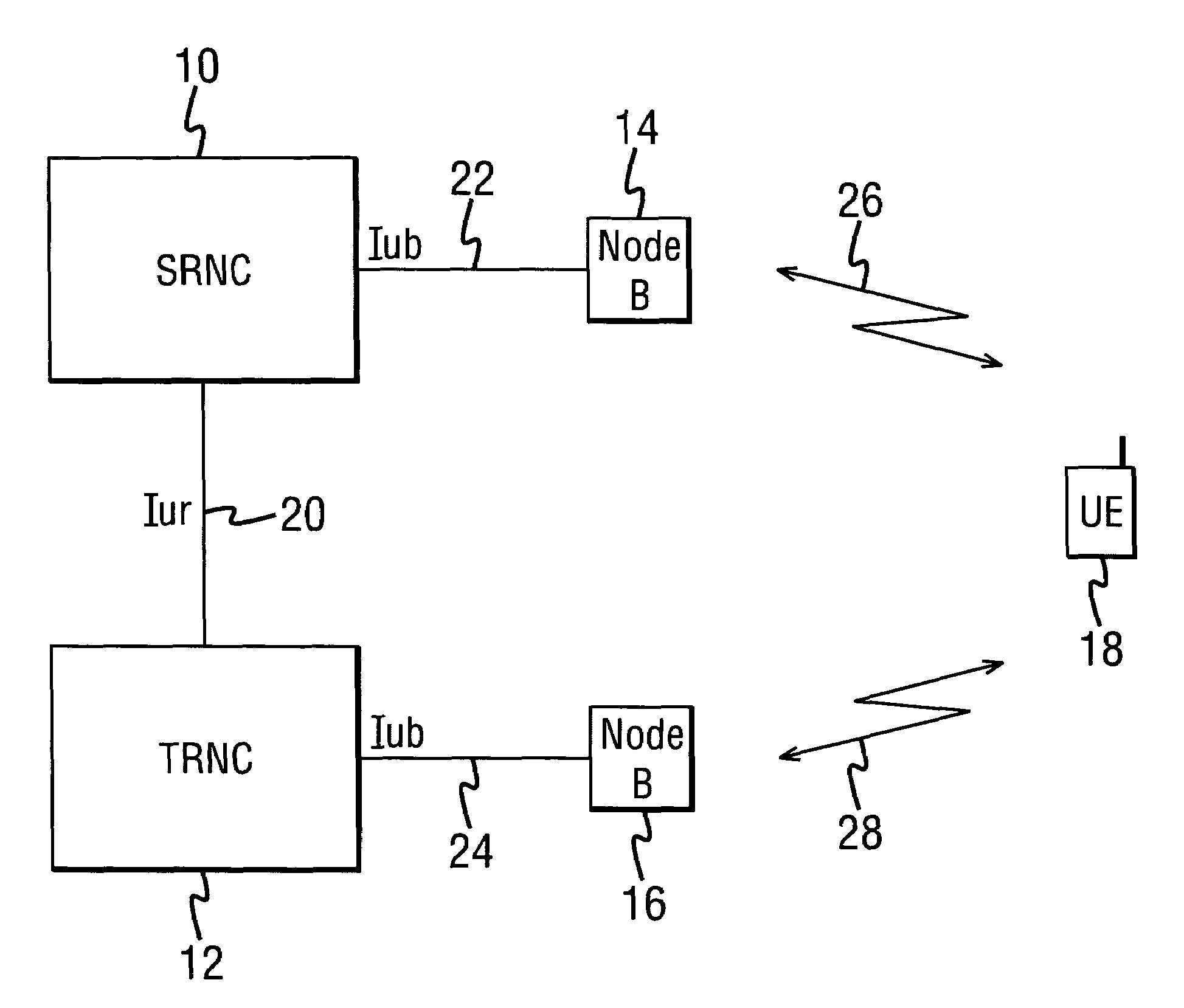
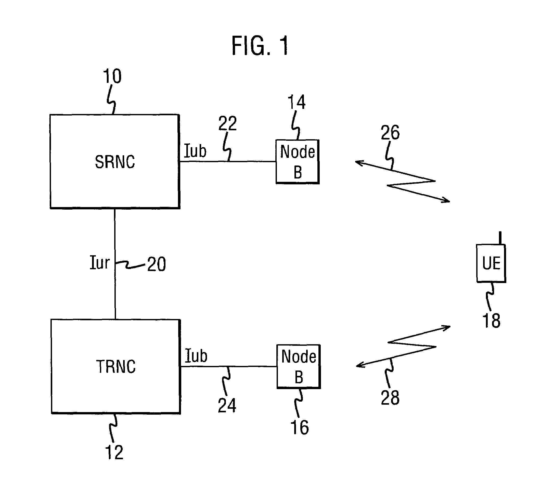
[0027]Referring to FIG. 1 there is illustrated an example of elements in a UMTS network architecture for describing an example implementation of the invention.

[0028]A source radio network controller (SRNC) 10 is connected to at least one base station, termed a “Node B”, 14 via an interface 22, preferably an Iub interface. A target radio network controller (TRNC) 12 is connected to at least one Node B 26 via an interface 24, again preferably an Iub interface. The SRNC 10 and the TRNC 12 are interconnected via an inter-RNC interface 20, preferably being the Iur interface. A user equipment (UE) 18 may establish a radio communication with any radio network controller via an associated Node B. In the example of FIG. 2, the UE 18 may establish a connection to Node B 14 via a radio link 26, and / or may establish a connection to Node B 16 via a radio link 28. The UE 18 is representative only, and in practice a plurality of UEs may establish radio links.

[0029]For the purpose of discussion of ...


PUM


Abstract

There is disclosed a method for serving radio network subsystem relocation from a first radio network controller to a second radio network controller for an established call to a user equipment, comprising transmitting a transmission power control combination index of a radio link established between the user equipment and the first radio network controller to the second radio network controller.

Description

FIELD OF THE INVENTION[0001]The present invention relates to serving radio network subsystem relocation in a mobile communications system.BACKGROUND OF THE INVENTION[0002]In the field of mobile communications, it is well know to provide for the relocation of the network access point of an established call to a user equipment as the user equipment roams in the network.[0003]A TPC (transmission power control) CI (combination index) is an integer value in the range 0 to 5. Each time a radio link is established, a TPC CI is allocated for the link. A radio link is a connection from a radio network controller (RNC) to a user equipment (UE) via a base station. All radio links established via a given base station (Node B) must have the same TPC CI. If a new radio link is established using a Node B which has no previous radio links, then a new non-used TPC CI must be allocated for that Node B.[0004]The UE uses the TPC CI to control the power for different radio links. Radio links from the sa...

Claims


Application Information

Patent Timeline
Patent Type & Authority Patents(United States)
IPC IPC(8): H04B7/00H04B7/005H04W36/10H04W52/02
CPCH04W36/10H04W52/02
Inventor SIPILA, JUHA P.GUSTAFSSON, STURE
Owner NOKIA TECH OY
Why Eureka
Try Eureka