
Method for positioning a scanning probe on a target track of a multi-track storage medium, storage device, scanning device, and storage medium

Active Publication Date: 2008-06-03
DAEDALUS BLUE LLC
View PDF7 Cites 9 Cited by
  • Summary
  • Abstract
  • Description
  • Claims
  • Application Information

AI Technical Summary

Benefits of technology

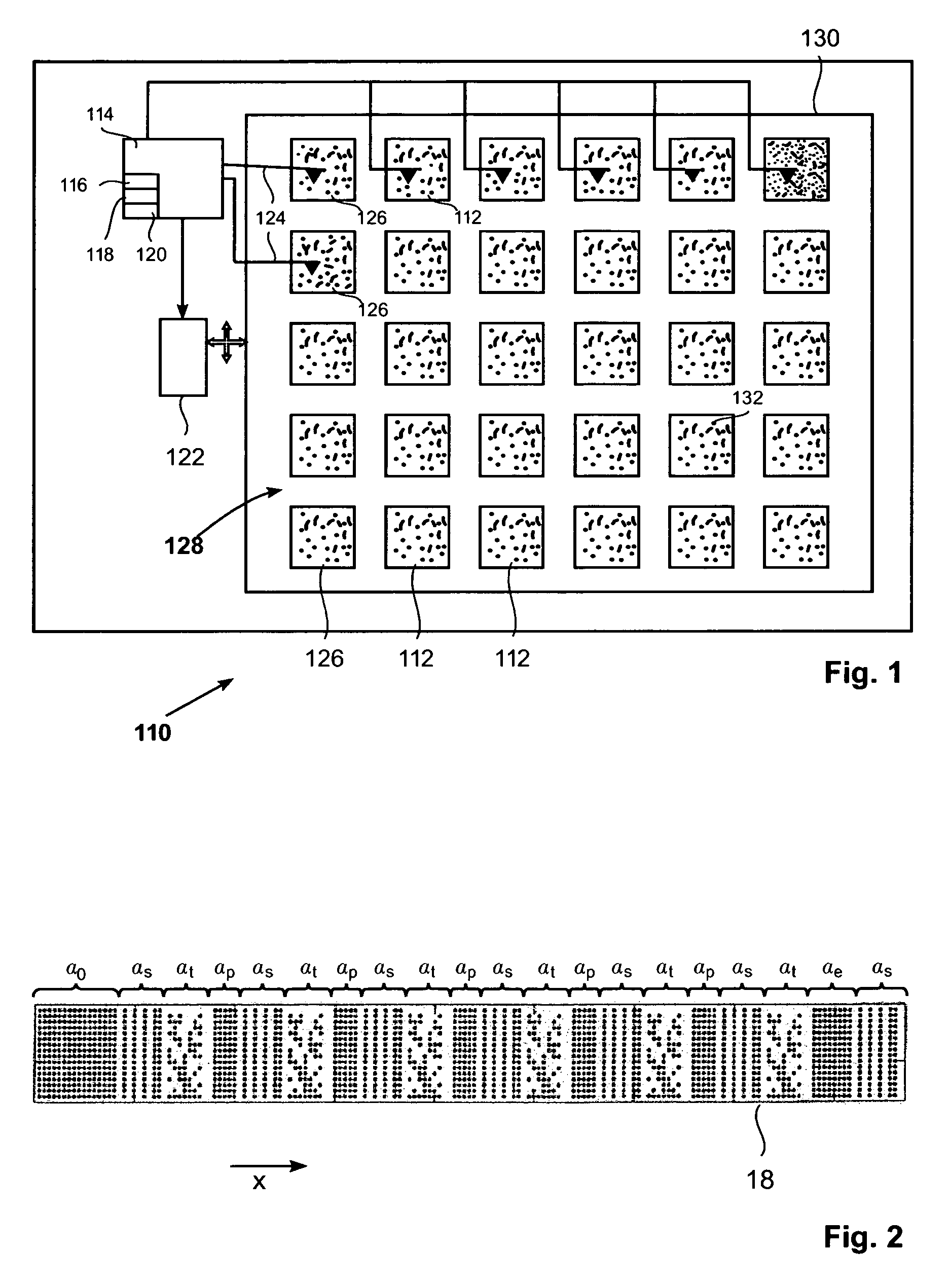
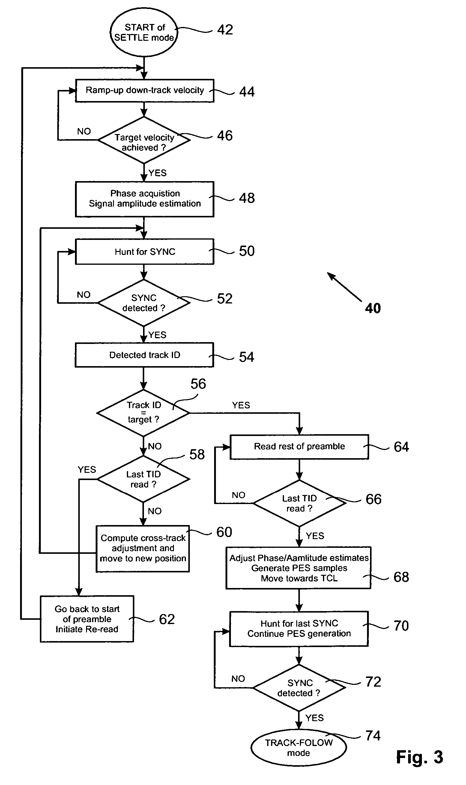
[0021]According to a very preferred embodiment of the present invention, each track comprises multiple track identifiers, each track identifier of a track identifying this particular track. By means of preparing the tracks this way, the method of positioning a scanning probe on a target track can be repeated many times while continuing scanning in scanning direction. In case only one track identifier is stored per track, the scanning probe would have to be repositioned on the beginning of a new track in order to identify the track identifier of this new track. As consequence, the scanner in x-direction would have to stop and go back to a x-position representing the beginning of a track. Instead, when having multiple track identifiers stored in each track the scanner can continue driving the scanning probe in scanning direction which is also referred to as x-direction in the following. Then the scanning probe has only to be shifted along the y-axis, resulting in a diagonal jump due to the maintained movement of the scanning probe in x-direction. Preferably, every track identifier pattern of a track is initiated by a corresponding synchronization pattern for identifying the beginning of a subsequent track identifier pattern. In between a track identifier pattern and a synchronization pattern identifying the beginning of the subsequent track identifier pattern, there is preferably arranged a buffer pattern. When maintaining scanning velocity in x-direction, a scanning probe will not land on the same x position where started from when jumping to another track. Without the buffer pattern introduced above the scanning probe would land somewhere within the synchronization pattern and would not be able to identify the synchronization pattern as such since the beginning of the synch pattern is missed. Thus, the buffer pattern allows repositioning of the scanning probe while maintaining the scanning velocity in x-direction and nevertheless identifying the entire synchronization pattern for reading the next track identifier of the new track.

Problems solved by technology

Consequently, in such a storage device it is a challenge to locate the precise track where information is to be written or from which information is to be read.

Method used


Image

  • Method for positioning a scanning probe on a target track of a multi-track storage medium, storage device, scanning device, and storage medium
  • Method for positioning a scanning probe on a target track of a multi-track storage medium, storage device, scanning device, and storage medium
  • Method for positioning a scanning probe on a target track of a multi-track storage medium, storage device, scanning device, and storage medium

Examples


Embodiment Construction

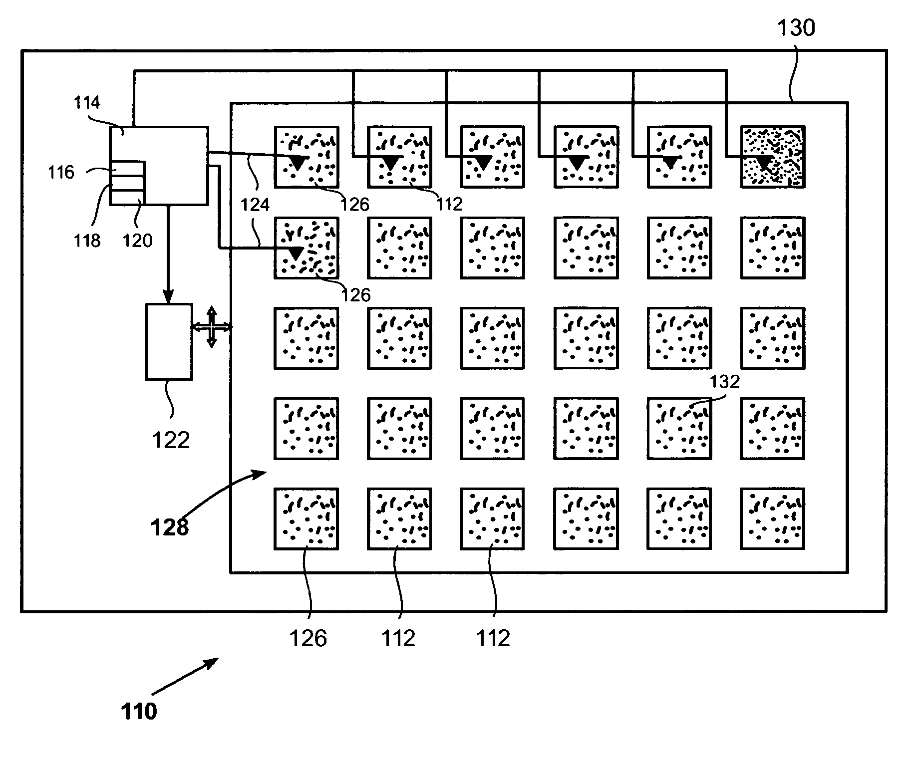
[0037]It should be emphasized that the techniques proposed in this description apply equally well to any storage device comprising an array of scanning probes. In addition to storage devices, it will be appreciated that embodiments may be implemented on any device or system that has an array of scanning probes or other transducers and a scanner. Although typically used for data storage, embodiments may be implemented in any application that requires scanner actuation. The following description is based on the storage device having a plurality of scanning probes disclosed in Vettiger 2000 and U.S. Pat. No. 5,835,477 as mentioned above for the sole purpose of illustration. Such a storage device 110 is shown in FIG. 1 of a top view of a storage medium 130 with a plurality of fields 128, for example six times five fields arranged in rows and columns. Each field comprises marks 132, and the fields include data fields 112 and operational data fields 126 which may be used to contain operat...


PUM

PropertyMeasurementUnit
velocityaaaaaaaaaa
phaseaaaaaaaaaa
distanceaaaaaaaaaa

Abstract

A method for settling on a target track of a servo system in a storage device (110) comprising a scanning probe (e.g., a scanning probe array system (124)) is disclosed, as well as a corresponding storage device (110). A data format is employed for the data stored in servo fields (18), consisting mainly of a preamble for assisting the settle process.

Description

FIELD OF THE INVENTION [0001]This invention relates to a storage device comprising a scanning probe, or probe array, a scanning device, a storage medium, and to a method for positioning a scanning probe on a target track of a multi-track storage medium.BACKGROUND OF THE INVENTION [0002]In the field of this invention an example of a storage device comprising a plurality of scanning probes is a micro-electro-mechanical system (MEMS) based scanning-probe data-storage system. A typical example of such a probe-based storage device that uses thermomechanical writing and thermomechanical or thermal reading by using heater cantilevers is disclosed in Vettiger et al., “The ‘Millipede’—More than one Thousand Tips for Future AFM Data-Storage,” IBM J. Res. Develop., Vol. 44, No. 3, pp. 323-340 (2000); and E. Eleftheriou et al., “Millipede-a MEMS-based scanning-probe data-storage system,” IEEE Trans. Magn., vol. 39, pp. 938-945 (2003). Such a system is also disclosed in U.S. Pat. No. 5,835,477 i...

Claims


Application Information

Patent Timeline
Patent Type & Authority Patents(United States)
IPC IPC(8): G11B7/00
CPCB82Y10/00G11B9/1454G11B11/007G11B2005/0021
Inventor CHERUBINI, GIOVANNIELEFTHERIOU, EVANGELOS S.POZIDIS, CHARALAMPOSSRI-JAYANTHA, SRI M.
Owner DAEDALUS BLUE LLC
Learn More