
Wireless communication enabled meter and network

Inactive Publication Date: 2008-05-27
ENDEAVOR MESHTECH +1
View PDF38 Cites 159 Cited by
  • Summary
  • Abstract
  • Description
  • Claims
  • Application Information

AI Technical Summary

Benefits of technology

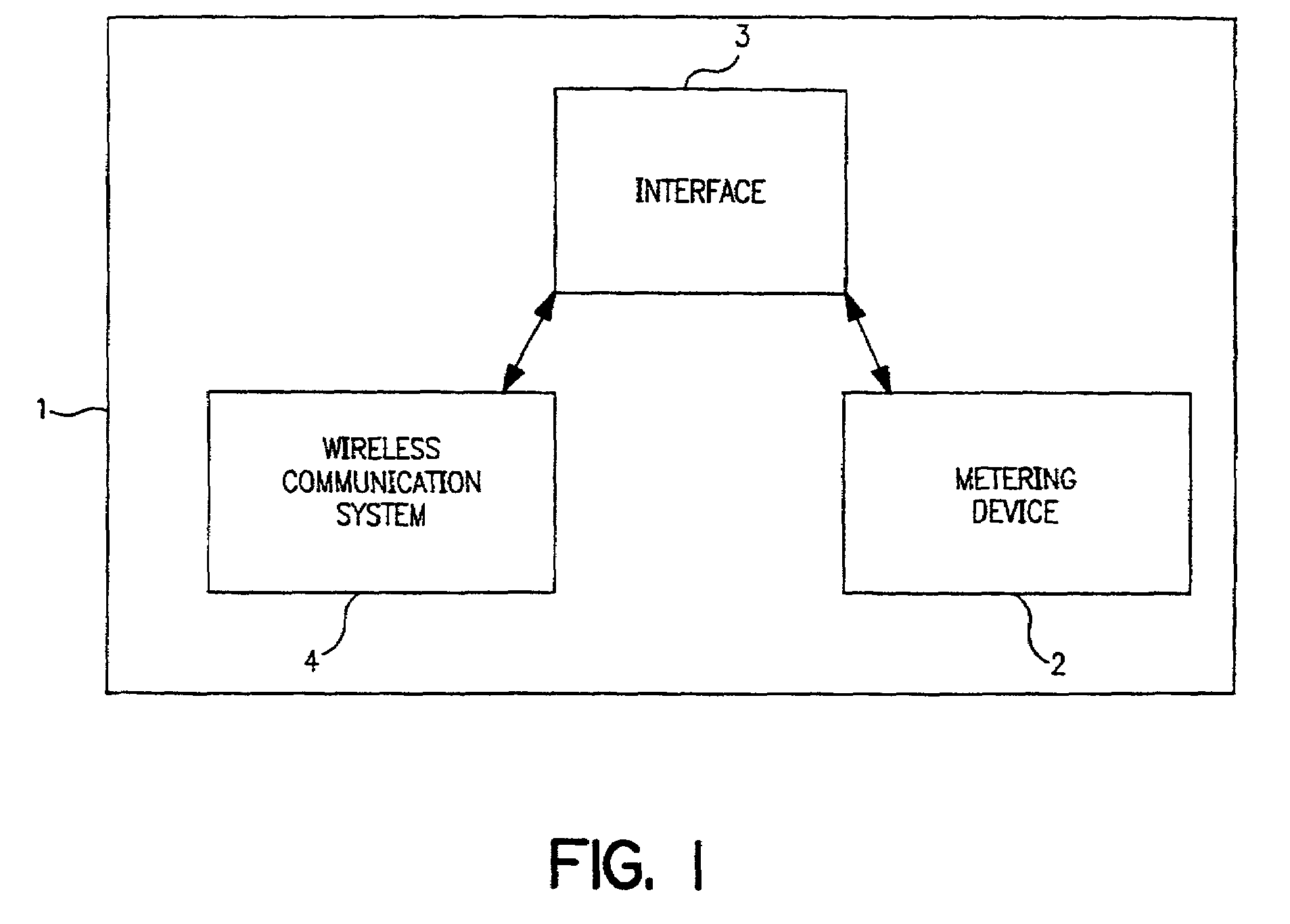
[0012]According to one embodiment, a wireless communication enabled meter is disclosed. A meter enabled for wireless communication comprises a metering device, a wireless communication system and an interface between the two. The metering device is a standard programmable metering device that can measure usage data and control usage. The wireless communication system is enabled for wireless communication using, e.g., the Bluetooth™ protocol. The interface facilitates communication between the metering device and the communication system so that meter data can be read with a wireless network using, e.g., the Bluetooth™ protocol.

Problems solved by technology

Communicating, via power lines or telephone lines is slow and subject to physical disruption.
Moreover, communicating via power lines or telephone lines presents the possibility of spurious signals, cross-talk, and other interference.
Both are expensive and two-way radios also require a license.
These networks are expensive to install and somewhat intrusive in that cables must be run to physically interconnect the various nodes in the network.
Moreover, networks that are interconnected with cables are subject to physical disruption of the cables.
Conventional wireless networks, however, have limitations as well.
For example, because conventional wireless networks generally have a loop configuration, when one node is disabled, the integrity of the entire network is affected.
Moreover, if the master node of such a conventional network is disabled, the network becomes isolated.
These and other drawbacks exist with current systems.

Method used


Image

  • Wireless communication enabled meter and network
  • Wireless communication enabled meter and network
  • Wireless communication enabled meter and network

Examples


Embodiment Construction

[0030]FIG. 1 schematically depicts a meter 1 that is enabled for wireless communication. Meter 1 may comprise metering device 2, interface 3 and wireless communication transceiver 4. In operation, metering device 2 may communicate with wireless communication transceiver 4 via interface 3. Wireless communication transceiver 4, in turn, may communicate with other wireless communication enabled devices, for example, other meters 1 or a central station. Wireless communication transceiver 4 may be operative to transmit data to and receive data from other meters 1 equipped with transceivers 4.

[0031]Metering device 2 operates to measure and regulate the usage of some utility, e.g., natural gas, electricity, or water. According to one embodiment, metering device 2 comprises any known metering device capable of producing an analog or digital output signal indicative of utility usage. In another embodiment, metering device 2 comprises a metering device capable of accepting an analog or digita...


PUM


Abstract

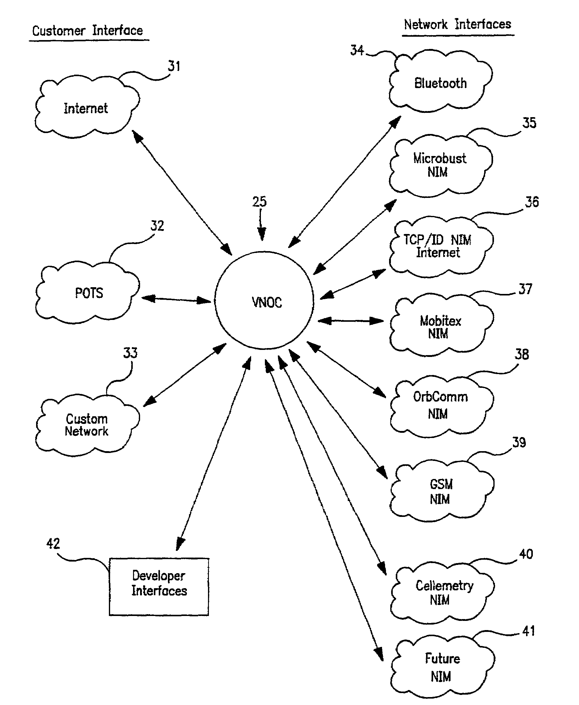
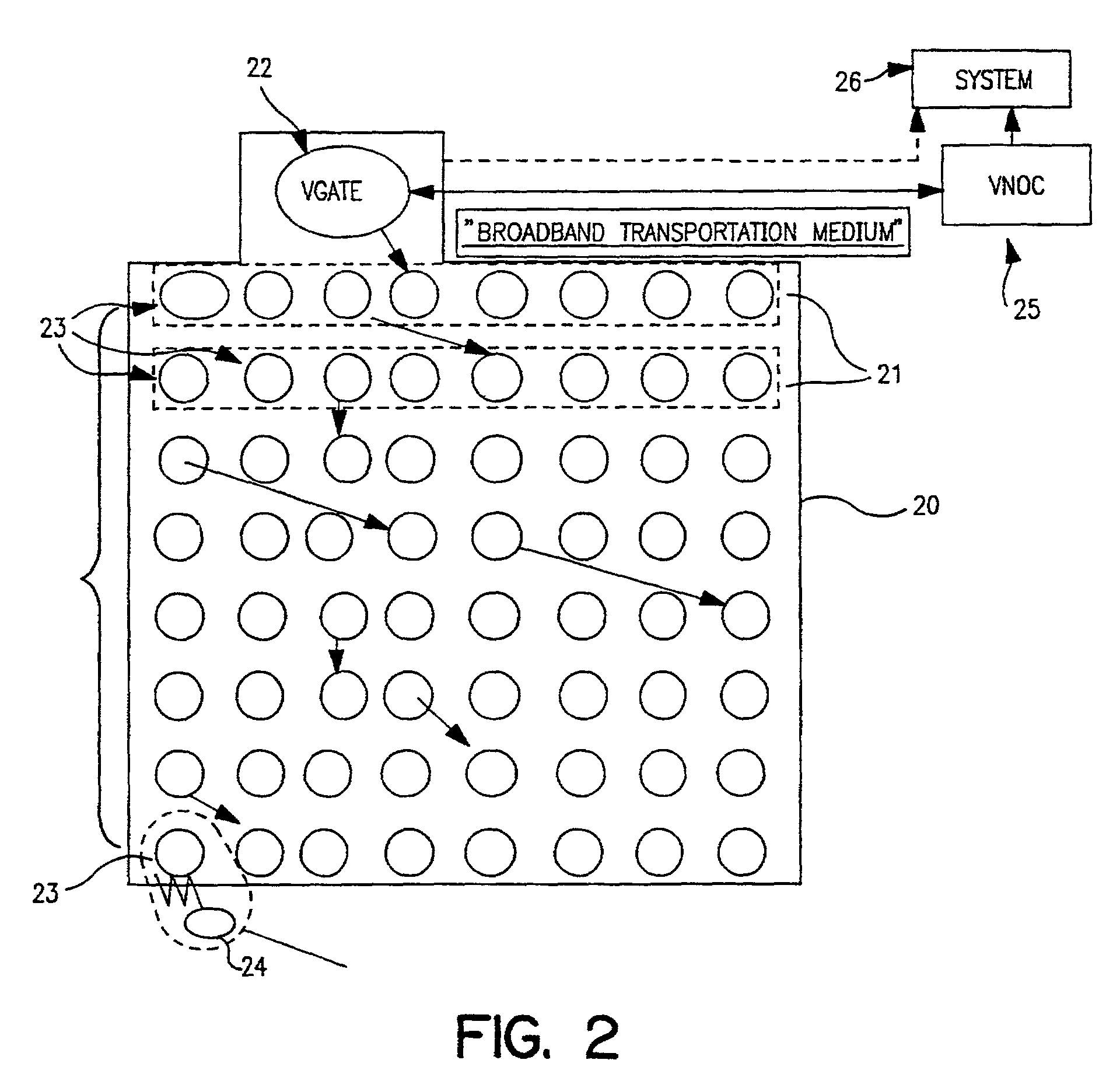
A meter enabled for wireless communication and a wireless communication network are disclosed. A meter enabled for wireless communication comprises a metering device, a wireless communication system and an interface between the two. Meter data can be read, and the meter can be controlled via communication with a wireless network using, e.g., the Bluetooth™ protocol. A self-configuring wireless network is also disclosed. The wireless network includes a number of vnodes, and one or more VGATES. The vnodes are devices that are enabled for wireless communication using, e.g., the Bluetooth™ protocol. Vnodes are operative to form ad hoc piconet connections. The one or more VGATES comprise computer network gateways that are enabled for wireless communication using, e.g., the Bluetooth™ protocol. Thus, the VGATES enable the wireless array of vnodes to communicate with a private or public computer network to transmit data or receive commands. The network may also communicate with a VNOC system. VNOC is a universal communications adapter that enables the wireless array of vnodes to communicate (either directly or through a VGATE) with a central control facility via various wireless or wired communication media.

Description

[0001]The present application claims priority under 35 U.S.C. § 120 of U.S. application Ser. No. 09 / 774,121, filed Jan. 31, 2001 and U.S. application Ser. No. 09 / 621,965, filed Jul. 21, 2000. This application also claims priority under 35 U.S.C. § 119 of U.S. provisional application Ser. No. 60 / 179,046, filed Jan. 31, 2000 and U.S. provisional application Ser. No. 60 / 179,041, filed Jan. 31, 2000. The entire contents of each of these applications are herein fully incorporated by reference.FIELD OF THE INVENTION[0002]This invention relates to a meter that is enabled for wireless communication. More specifically, this invention relates to a meter, such as a utility meter, that is enabled for wireless communication. The invention also relates to a self-configuring, wireless network that enables data capture at a plurality of metering sites and wireless transmission of the captured data from the plurality of metering sites to one or more collection points.BACKGROUND OF THE INVENTION[0003...

Claims


Application Information

Patent Timeline
IPC IPC(8): G06F15/177G06F17/00H04L12/56
CPCG01D4/002H04W84/18Y02B90/246Y04S20/42Y02B90/241Y04S20/32Y02B90/20Y04S20/30G01D2204/45
Inventor ELLIOTT, KARL E.GARRARD, KENNETH W.
Owner ENDEAVOR MESHTECH
Learn More