
Door handle

a door handle and handle technology, applied in the field of semiautomatic systems, can solve the problems of automatic system failure once again, user frustration,

Inactive Publication Date: 2008-05-20
KEY PLASTICS
View PDF12 Cites 95 Cited by
  • Summary
  • Abstract
  • Description
  • Claims
  • Application Information

AI Technical Summary

Benefits of technology

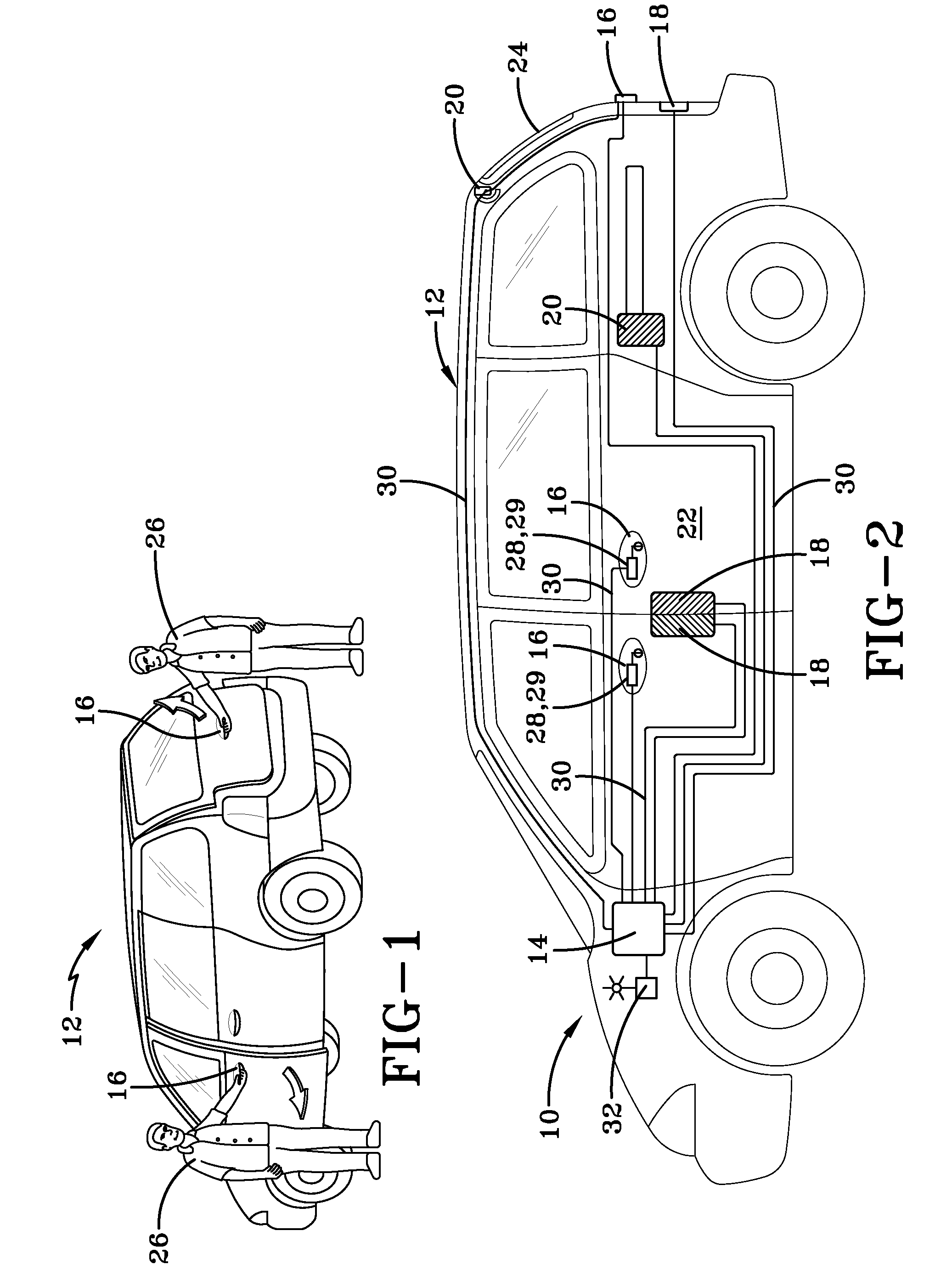
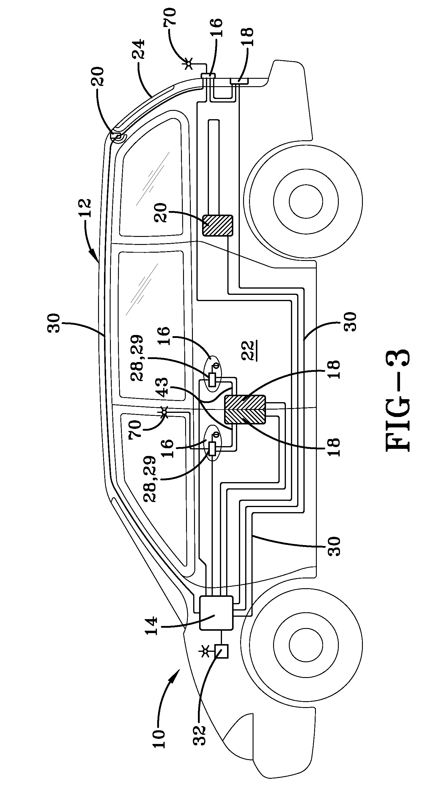
[0007]A handle for exterior use in a vehicle to authorize a mechanism to unlatch an access door has a structural part; a cover; and a pair of sensors or switches between the structural part and the cover. A first sensor or switch to interact with one or more fingers of a user's hand and a second sensor or switch spaced from said first sensor to be activated by a user's different finger or the user's thumb. The combination of the two switches or sensors signal the mechanism to unlatch the access door and wherein the activation of only the second sensor or switch in the absence of touching the first sensor or switch authorizes a mechanism to lock the access door.

Problems solved by technology

One basic problem with these fairly new automatic locking / unlocking and latching / unlatching systems is the degree of frustration they create in the user.
More often than not, the user will attempt to open the door that he or she believes to be unlocked only to find that the automatic system has once again failed, in the context of not placing the door in the physical state that is desired by the user.
While a vast improvement over the more conventional systems, this handle still provided the same problem of identifying the status of the lock / unlock condition and therefore, similar to the prior art devices, the ability to unlatch the door is still dependent on the locked / unlocked status of the door.

Method used


Image

  • Door handle
  • Door handle
  • Door handle

Examples


Embodiment Construction

[0015]It is to be understood the present invention may be embodied in other specific forms without departing from the scope of the invention. The illustrated and described embodiments are to be considered in all respects only as illustrative and not restrictive. The scope of the invention is, therefore, indicated by the appended claims rather than by the description. All changes that come within the meaning and range of equivalency of the claims and included elements are to be embraced within their scope.

[0016]Referring now to FIGS. 1 and 2, an embodiment of the present invention is shown and described. The invention includes, among other things, a system arrangement 10 that is suitable for use in a vehicle 12 to facilitate opening or unlatching of various access doors, including without limitation, vehicle doors, liftgates, panels, trunk lids, hoods or other points of access. System 10 can be used for example, without limitation, in connection with trunk latches, flip-glass latches...


PUM


Abstract

A handle 16 for exterior use in a vehicle to authorize a mechanism (18) to unlatch an access door has a structural part (34); a cover (36); and a pair of sensors or switches (28, 29) between the structural part (34) and the cover (36). A first sensor or switch (28) to interact with one or more fingers of a user's (26) hand (2) and a second sensor or switch (29) spaced from said first sensor (28) to be activated by a user's (26) different finger or the user's (26) thumb. The combination of the two switches or sensors (28, 29) signal the mechanism (18) to unlatch the access door and wherein the activation of only the second sensor or switch (29) in the absence of touching the first sensor or switch (28) authorizes a mechanism (18) to lock the access door. Preferably, the first and second sensors or switches (28, 29) are electrically coupled such that activation of both authorizes an unlatching of the access door while the activation of only the second sensor or switch (29) authorizes a lock only feature. Accordingly, the second sensor or switch (29) changes authorization from unlatch to lock dependent on the use or non-use of the first sensor or switch (28).

Description

FIELD OF THE INVENTION[0001]The present invention generally relates to a semi-automatic system for unlatching vehicle doors, hatches, trunks, liftgates and other entryways. More particularly to a system that is more user-friendly than currently available systems.BACKGROUND OF THE INVENTION[0002]The present invention is useful in the automotive arts; however, it is generally applicable to any type of door, liftgate or window. By way of background, a number of functions or processes are needed to open a door. Consider a typical automotive door that is closed and one that has been locked, for example by sensing the presence of a certain type of passive sensor, manually activating a key-fob, pressing a button or manually with a key. To move this door from its closed position within its frame to an open position the door must be moved from a locked condition to an unlocked condition. As can be appreciated, in these orientations the door is still fixed to its frame and in a closed positio...

Claims


Application Information

Patent Timeline
IPC IPC(8): H01H3/16
CPCE05B81/78H01H9/06E05B81/04E05B81/14E05B81/77G07C2009/00206
Inventor PUDNEY, RICHARD I.
Owner KEY PLASTICS
Learn More