
Photovoltaic power generation system

a photovoltaic power generation and photovoltaic technology, applied in the direction of electric variable regulation, process and machine control, instruments, etc., can solve the problems of inability to meet the required capacity of electric power generation, inability to control the output electric power of the respective solar cell strings, and inability to meet the requirements of electric power generation

Inactive Publication Date: 2008-05-13
KYOCERA CORP
View PDF10 Cites 187 Cited by
  • Summary
  • Abstract
  • Description
  • Claims
  • Application Information

AI Technical Summary

Benefits of technology

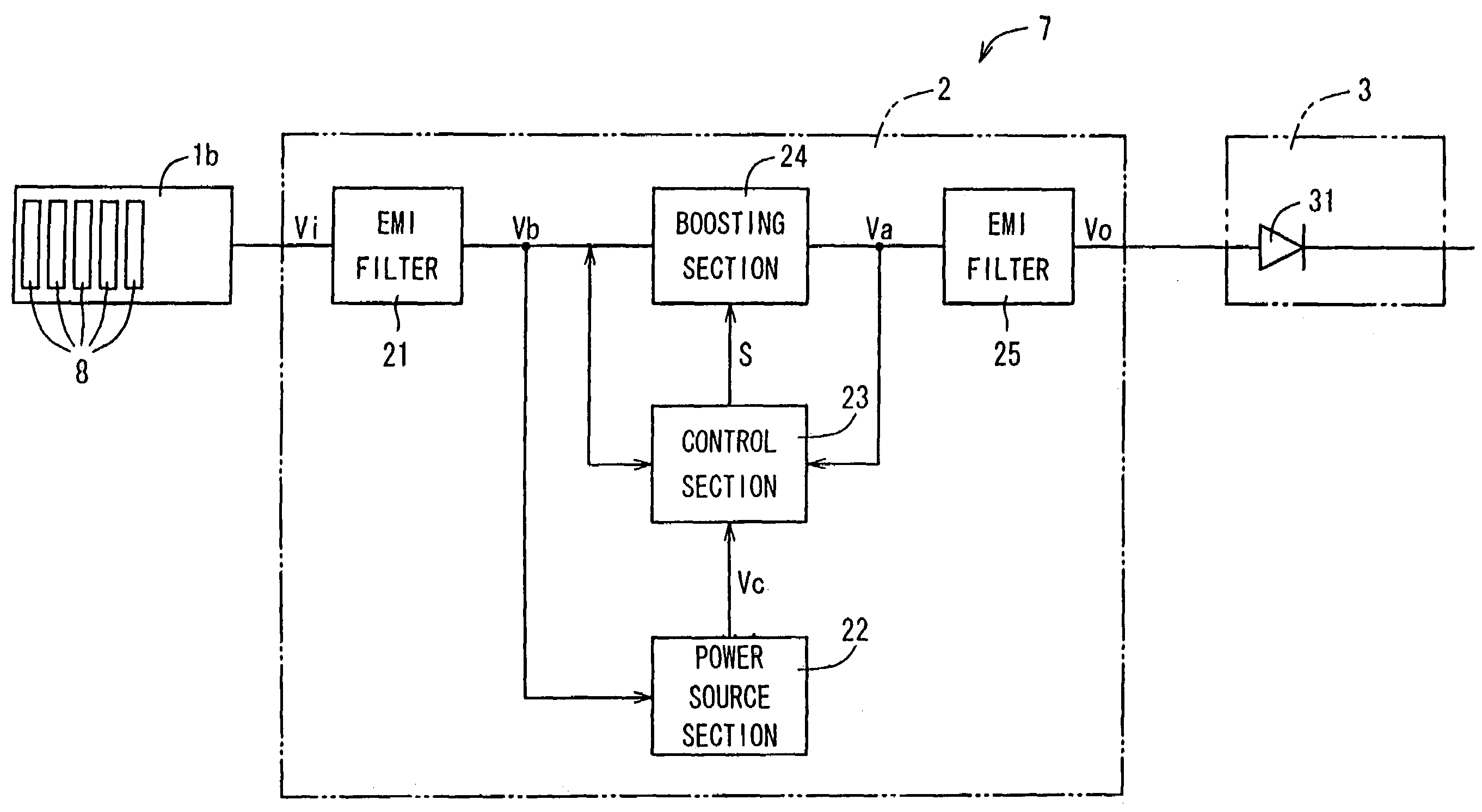
[0013]In consideration of the problems in a photovoltaic power generation system as described above, an object of the invention is to provide a photovoltaic power generation system capable of achieving system linkage of a plurality of solar cell strings having different output voltages to a commercial electric power system in a simple way, which enables efficient use at the maximum output electric power of the solar cell strings, and which does not cause the problem of wrong setting of a boosting ratio.

Problems solved by technology

However, since the power conditioner 14 controls output electric power of the solar cell strings as a result of collection in the connection box 13, it is impossible to control output electric power of the respective solar cell strings 11a, 11b.
Moreover, since the unit of expansion of the solar cell modules 18 is a string unit, there arises a case that a difference is made between a necessary capacity of electric power generation and an actual installable capacity, and it is impossible to cause a remaining installable area smaller than that of an installation region of one solar cell string to contribute to electric power generation, with the result that such a problem arises that it is impossible to satisfy a required capacity of electric power generation.
However, in the above method, because it is required to manually select a boosting voltage ratio by using a contact selection switch disposed to the voltage regulating means at the time of installation of the photovoltaic power generation system, the man-hours at the time of installation increase, and moreover, in the case of mistakenly setting the contact selection switch, an output corresponding to the installation number of the solar cell modules 18 cannot be obtained, and such a problem arises that the photovoltaic power generation system does not work properly.
However, since the boosting voltage ratio is fixed, such a problem arises that it is impossible to obtain the true maximum output electric power.

Method used


Image

  • Photovoltaic power generation system
  • Photovoltaic power generation system
  • Photovoltaic power generation system

Examples


Embodiment Construction

[0110]Now referring to the drawings, preferred embodiments of the invention are described below.

[0111]Below, an embodiment of a photovoltaic power generation system relating to the present invention will be described in detail based on drawings which show diagrammatically. The same components as those described before will be denoted by the same reference numerals, and a repetition of a description thereof will be omitted.

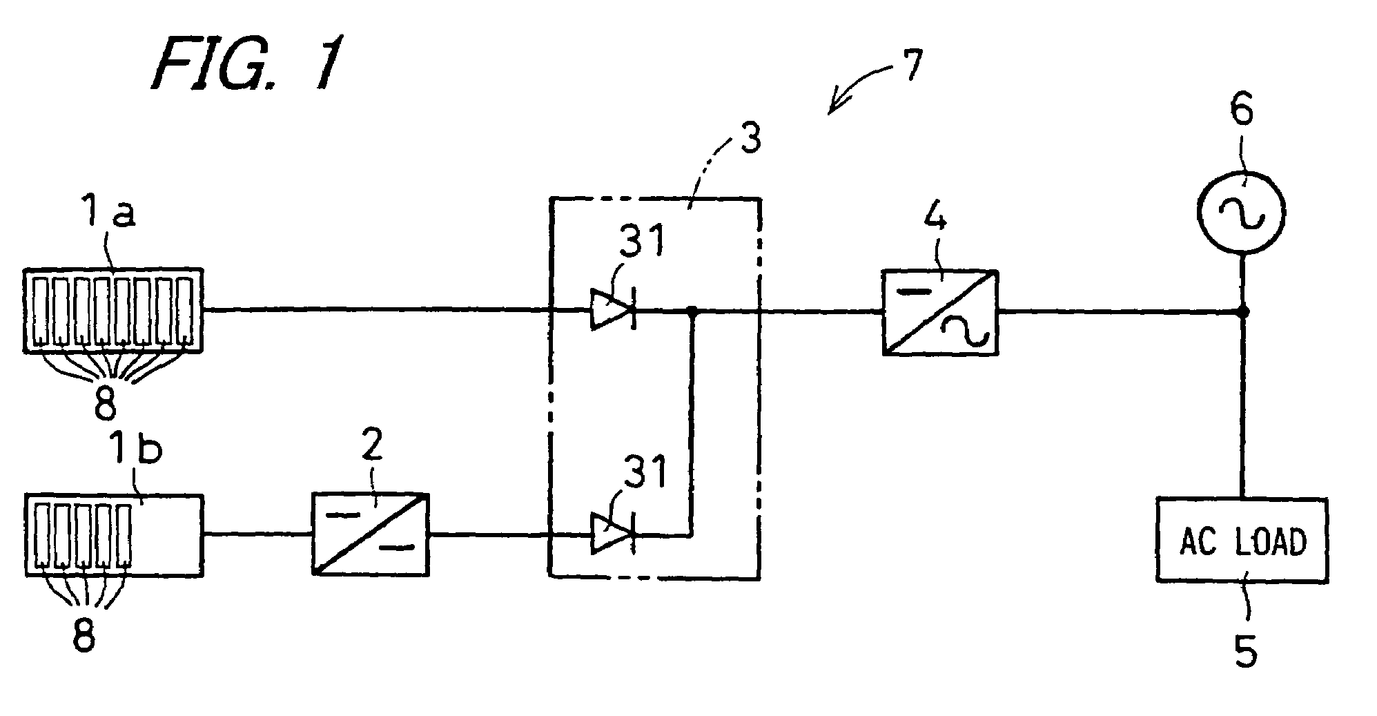
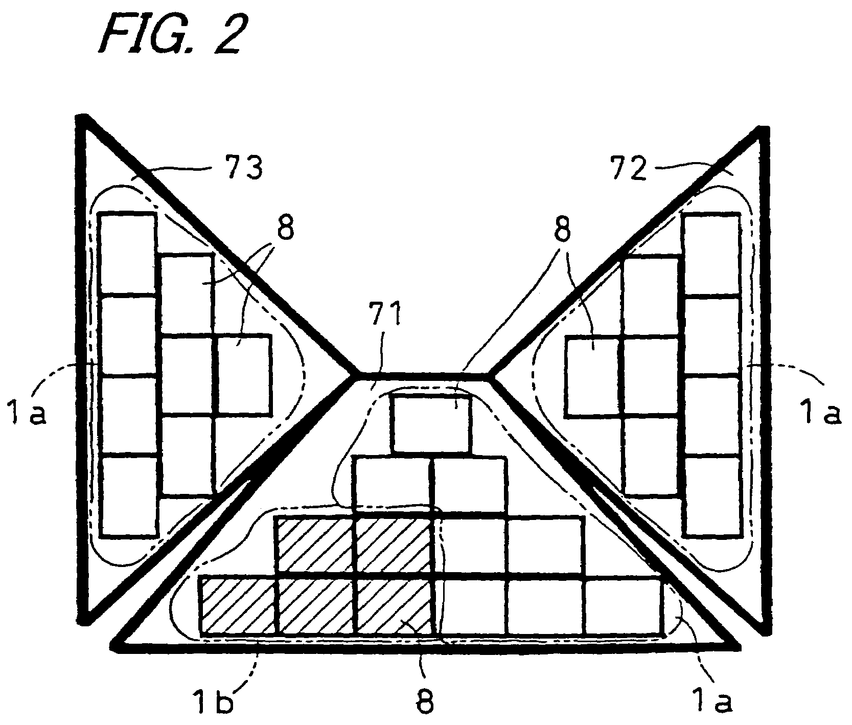
[0112]FIG. 1 is a block diagram showing a photovoltaic power generation system 7 of an embodiment of the invention. As shown in FIG. 1, this photovoltaic power generation system 7 comprises a first solar cell string 1a which is connected to a backflow prevention diode 31 included in a connection box 3, and includes solar cell modules 8 connected in series, which are solar cell element groups having a plurality of solar cell elements connected to each other, that is, solar cells of a predetermined standard number, and a second solar cell string 1b which is connected...


PUM


Abstract

An object of the present invention is to provide a photovoltaic power generation system which is capable of achieving system linkage of a plurality of solar cell strings having different output voltages to a commercial electric power system with ease, and which enables efficient use of the maximum output electric power. It is a photovoltaic power generation system characterized by disposing voltage regulating means that regulates a DC voltage outputted from non-standard solar cell string between a standard solar cell string and electric power converting means, and regulating an output voltage of the non-standard solar cell string to the side of an output voltage of the standard solar cell string by the use of the voltage regulating means.

Description

BACKGROUND OF THE INVENTION[0001]1. Field of the Invention[0002]The present invention relates to a photovoltaic power generation system that increases alternatives to allow connection of solar cell elements or solar cell element groups (solar cell modules) used for composing a solar cell string installed on a structure such as a roof and that enables accurate tracking of the maximum output point of a solar cell string.[0003]2. Description of the Related Art[0004]FIG. 21 is a block diagram showing a related art photovoltaic power generation system 17. As show in FIG. 21, there is conventionally proposed a photovoltaic power generation system 17 made by connecting a plurality of solar cell strings 11a, 11b in parallel and composed so as to enable acquirement of a maximum output electric power from the solar cell strings 11a, 11b. This photovoltaic power generation system 17 comprises solar cell strings 11a, 11b, each of which is made of a plurality of solar cell elements connected to ...

Claims


Application Information

Patent Timeline
Patent Type & Authority Patents(United States)
IPC IPC(8): H01L31/042H01L31/00H02J3/38
CPCH01L31/042Y02E10/563Y10S323/905H02J3/383H01L31/02021H02J2300/26H02J2300/24H02J3/381Y02E10/56H02J3/46
Inventor SUENAGA, TAKASHIHIGUCHI, TANEO
Owner KYOCERA CORP
Learn More