Frame structure for hi-hat assembly

a hi-hat and frame structure technology, applied in the field of percussion equipment improvement, can solve the problems of occupying a large storage space and prone to damage of hi-hat cymbals

Inactive Publication Date: 2008-05-13
PEARL DRUMS
View PDF14 Cites 6 Cited by
  • Summary
  • Abstract
  • Description
  • Claims
  • Application Information

AI Technical Summary

Problems solved by technology

Because the foot pedal is perpendicularly extended from a foot pedal holder assembly at the bottom side of the center shaft, it tends to be damaged during transportable of the hi-hat cymbal.
Further, because the foot pedal mechanism is not collapsible, the hi-hat cymbal occupies much storage space when not in use.

Method used


Image

  • Frame structure for hi-hat assembly
  • Frame structure for hi-hat assembly
  • Frame structure for hi-hat assembly

Examples


Embodiment Construction

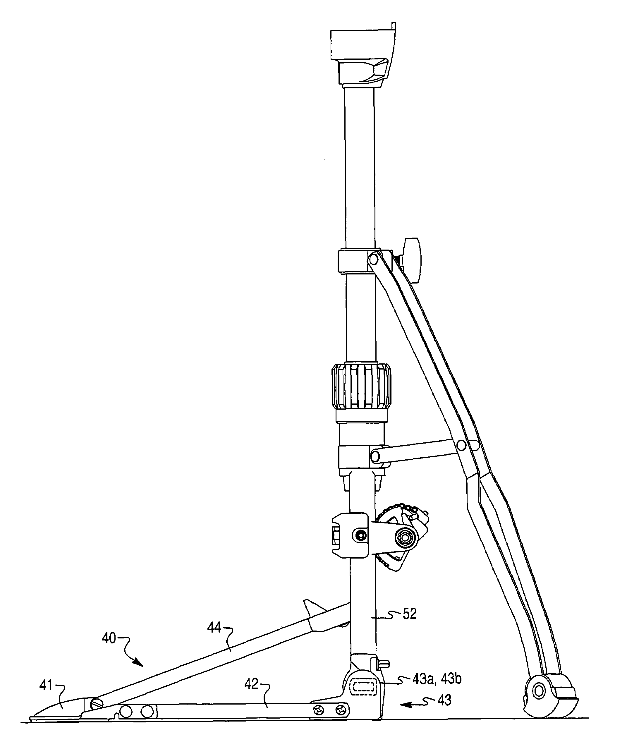
[0019]With reference to FIG. 3, the foot-operated pedal assembly 40 illustrated herein includes a pair of forwardly longitudinally elongated struts 42 to which a foot-operated pedal 44 is pivotally attached. Each elongated strut is provided with detachable fastening means 43 at its forward end. The fastening means 43 permits the pedal assembly 40 to be attached / detached from the pair of upright posts 52 through a male-female connector assembly. The fastening means 43 on the pedal assembly consists of forwardly facing hubs 43a and inwardly facing tangs 43b. The inwardly facing tangs 43b engage post clamps 52a provided on each upright post 52 by inserting the tangs 43b at an angle α in the direction of arrow A then rotated in the direction position shown by arrow B (see FIGS. 4 to 6). The inwardly facing tangs 43b are locked in place by rotating the pedal assembly 40 in the direction of arrow B (see FIG. 6) and by tightening the locking screw or nut member 51a threadingly disposed on ...


PUM


Abstract

A percussion system for a percussion instrument, comprising: a cymbal or other percussion mechanism; an upright elongated support; a base frame from which the support extends upwardly; a drive linking system movable to actuate the sound generating mechanism; and a foot-operated pedal assembly. The pedal assembly actuates the sound generating mechanism through the drive linking system with the pedal assembly being selectively connected to the base frame in one of a play mode or a docking mode. In the play mode, the pedal assembly is connected in a horizontal orientation along a ground surface in which the pedal is adapted to actuate the sound generating mechanism, and in the docking mode the pedal assembly is connected to the base frame in a vertical orientation along the base frame whereby the pedal assembly is connected to a docking station for ease of storage and transport.

Description

BACKGROUND OF THE INVENTION[0001]a) Field of the Invention[0002]This invention relates generally to improvements in percussion equipment; more particularly, the invention provides an enhanced pedal system having a detachable pedal assembly that may be stored in a docking station to thereby enhance storage and transport of the equipment.[0003]b) Description of Related Art[0004]Current hi-hat systems include a drive chain or strap directly connecting the foot pedal to a vertically movable rod that drives an upper movable cymbal to strike a lower fixed cymbal. Prior art FIGS. 1 and 2 typify such a foot pedal assembly.[0005]The percussion instrument 10 includes multiple, relatively telescoping sections. These include for example upper section 11 telescopically receivable within the lower section 12. A clamp 14 mounted at 15 on the upper section of section 12 is manually operable to clamp a friction ring against the side of section 11, thereby to retain the sections in the position shown...

Claims


Application Information

Patent Timeline
Patent Type & Authority Patents(United States)
IPC IPC(8): G10D13/02
CPCG10D13/065
Inventor TANAKA, YUKIO
Owner PEARL DRUMS
Why Eureka
Try Eureka