Wiring harness holding device
a holding device and wiring harness technology, applied in the direction of insulated conductors, electric/fluid circuits, cables, etc., can solve the problems of reducing the size of the wiring harness holding device, so as to reduce the production of looseness in the wiring harness, reduce the stress acting on the wiring harness, and improve general-purpose properties
- Summary
- Abstract
- Description
- Claims
- Application Information
AI Technical Summary
Benefits of technology
Problems solved by technology
Method used
Image
Examples
first embodiment
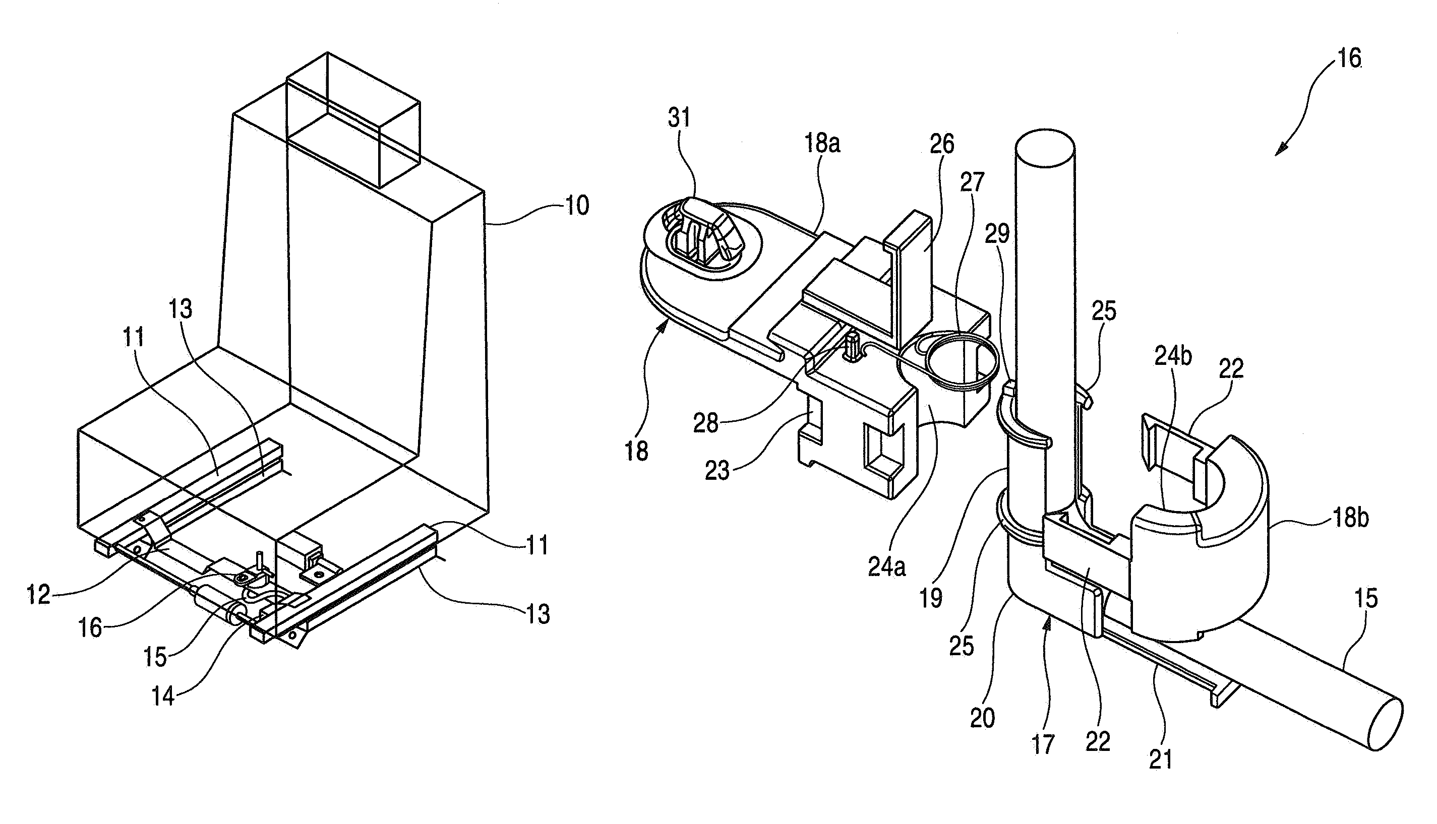
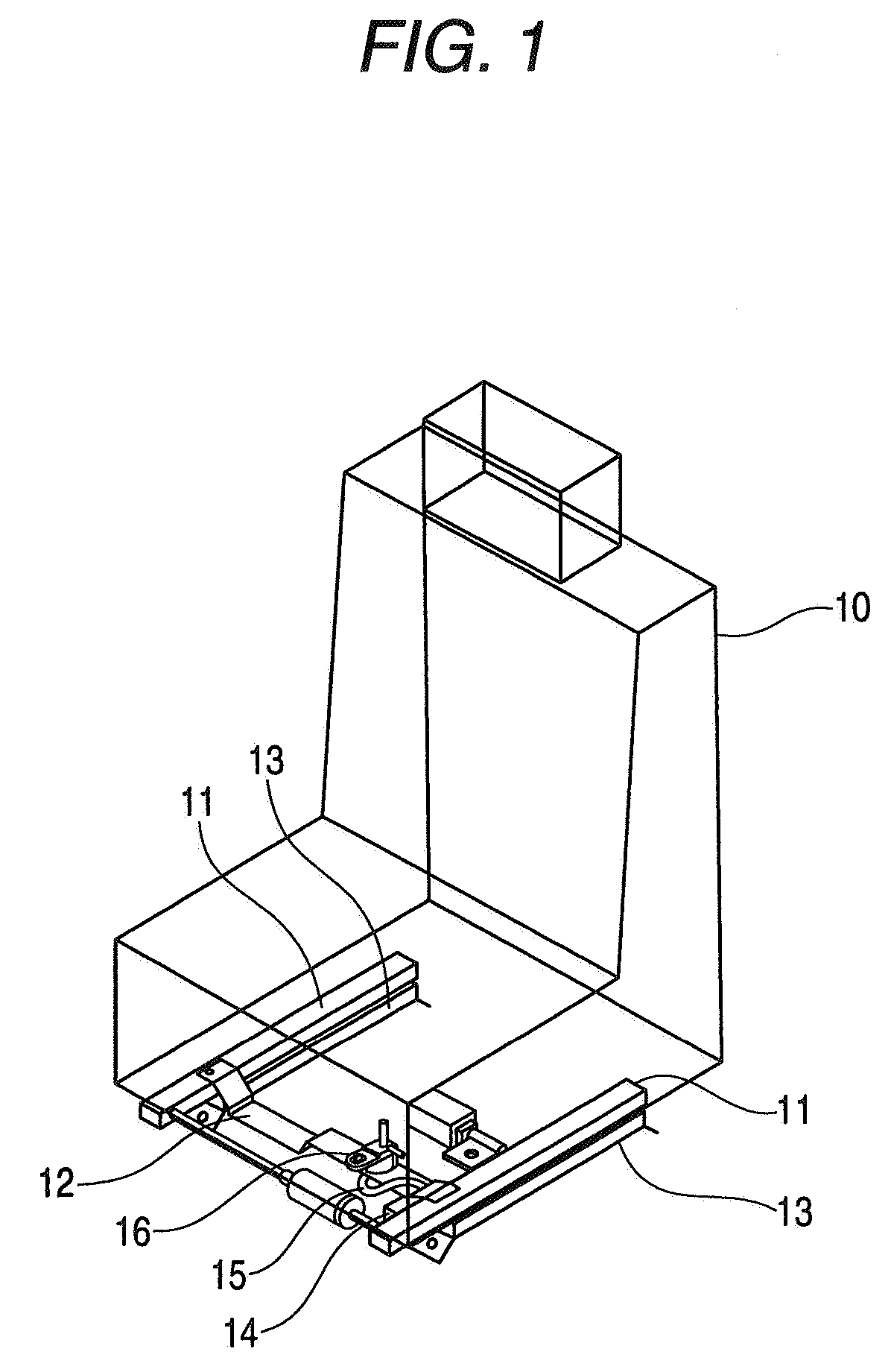
[0075]FIG. 1 is a perspective view of a vehicle sliding seat to which a wiring harness holding device of the invention is applied, FIG. 2 is an exploded perspective view of a movable side holding portion of the wiring harness holding device shown in FIG. 1, FIG. 3 is a perspective view showing an external appearance of the movable side holding portion which has been assembled completely, and FIG. 4 shows plan views of the vehicle sliding seat as viewed from a bottom side thereof which explain the operation of the wiring harness holding device shown in FIG. 1.
[0076]Firstly, a sliding construction of a vehicle sliding seat will be described.
[0077]As shown in FIG. 1, a pair of sliders 11 which extend in a back and forth or longitudinal direction of a vehicle body (not shown) are mounted on a bottom side of a vehicle sliding seat (a movable structure) 10 in such a manner as to be spaced apart in a width direction of the seat 10, and front end portions of the individual sliders 11 are co...
second embodiment
[0097]Next, referring to FIG. 5, the invention will be described below.
[0098]FIG. 5 is a perspective view of a movable side holding portion of a wiring harness holding device according to a second embodiment of the invention. Note that like reference numerals will be imparted to like or corresponding members to those of the first embodiment that has been described above, so as to omit the description thereof.
[0099]As shown in FIG. 5, the wiring harness holding device of the second embodiment is such that in the movable side holding portion 16 of the wiring harness holding device of the first embodiment that has been described above, a restriction rib 34 is provided at an upper collar portion 25 of a shaft portion 19 of a protector 17 in such a manner as to protrude radially, and a restriction rib 35 is provided at an upper opening edge portion of a through hole 24 of a support member 18 with which the collar portion 25 is in engagement in such a manner as to be situated on the same ...
third embodiment
[0100]Next, referring to FIGS. 6 to 11, the invention will be described below.
[0101]FIG. 6 is an exploded perspective view of a movable side holding portion of a wiring harness holding device of a third embodiment of the invention, FIG. 7 is a perspective view showing an external appearance of part of the movable side holding portion shown in FIG. 6 which explains an assembling procedure thereof, FIG. 8 is a perspective view showing an external view of the remaining part of the movable side holding portion shown in FIG. 6 which explains an assembling procedure thereof, and FIG. 9 is a perspective view showing an external view of the movable side holding portion shown in FIG. 6 which has been assembled completely. Note that like reference numerals will be imparted to like members to those of the first embodiment that has been described before, so as to omit the description thereof.
[0102]In a wiring harness holding device of this embodiment, a movable side holding portion 56 shown in ...
PUM
 Abstract
Description
Claims
Application Information
 - R&D
- Intellectual Property
- Life Sciences
- Materials
- Tech Scout
- Unparalleled Data Quality
- Higher Quality Content
- 60% Fewer Hallucinations
Browse by: Latest US Patents, China's latest patents, Technical Efficacy Thesaurus, Application Domain, Technology Topic, Popular Technical Reports.
© 2025 PatSnap. All rights reserved.Legal|Privacy policy|Modern Slavery Act Transparency Statement|Sitemap|About US| Contact US: help@patsnap.com


